


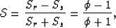
Next: A Fourier domain look
Up: Rosales and Biondi: PS-ADCIG
Previous: Introduction
This section describes the kinematic equation that transforms a
subsurface offset-domain CIG to an opening-angle-domain CIG,
for the converted-mode case.
The derivation follows the well-known equations for apparent slowness
in a constant-velocity medium in the neighborhood of the reflection/conversion
point. Our derivation is consistent with those presented by
Fomel (1996);Sava and Fomel (2000); and
Biondi (2005).
The expressions for the partial derivatives of the total
traveltime with respect to the image point coordinates are
as follows Rosales and Rickett (2001a):
| 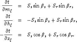 |
|
| |
| (1) |
Where Ss and Sr are the slowness (inverse of velocity) at the
source and receiver locations.
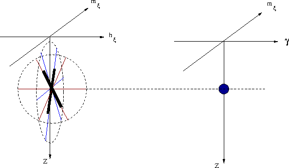
Figure ![[*]](http://sepwww.stanford.edu/latex2html/cross_ref_motif.gif) illustrates all the angles in this discussion. The angle
illustrates all the angles in this discussion. The angle  is the
direction of the wave propagation for the source, and the angle
is the
direction of the wave propagation for the source, and the angle  is the
direction of the wave propagation for the receiver.
Through these set of equations, we obtain:
is the
direction of the wave propagation for the receiver.
Through these set of equations, we obtain:
| 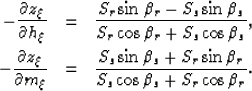 |
|
| (2) |
We define two angles,  and
and  , to relate and
as follows:
, to relate and
as follows:
| 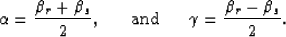 |
(3) |
angles
Figure 1 Angle definition for the kinematic
equation of converted mode ADCIGs
|
|  |

The meaning of the angles and will become clear later
in the paper; for now, we will refer to as the full-aperture angle.
Through the change of angles presented on equation (3),
and by following basic trigonometric identities,
we can rewrite equations (2) as follows:
| 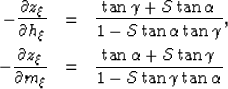 |
|
| (4) |
where,
|  |
(5) |
and  is the velocity ratio, as for example the P-to-S velocity ratio.
This leads to quadratic equations for
is the velocity ratio, as for example the P-to-S velocity ratio.
This leads to quadratic equations for
 and
and  as follows:
|  |
|
| (6) |
Each equation has two solutions, which are:
| ![\begin{eqnarray}
-\tan{\gamma} &=& \frac{\mathcal{S}^2 -1 \pm
\sqrt{ (1-\mathca...
...S}-
\frac{\partial z_\xi}{\partial m_\xi} \mathcal{S}^2 \right]}.\end{eqnarray}](img19.gif) |
|
| (7) |
The first of equation (7) provides the transformation from
subsurface offset-domain CIG into angle-domain CIG for the
converted-mode case.
This theory is valid under the assumption of constant velocity. However, it
remains valid in a differential sense in an arbitrary-velocity medium, by
considering that  is the subsurface half offset. Therefore, the limitation of
constant velocity is on the neighborhood of the image. For
is the subsurface half offset. Therefore, the limitation of
constant velocity is on the neighborhood of the image. For  , it is important
to consider that every point of the image
, it is important
to consider that every point of the image  is related to a point on the velocity model with the same coordinates.
In order to implement this equation, we observe that this can be done by an slant-stack
transformation as presented on
Figure . Note that
the contribution along the midpoints is a correction factor needed in order to perform
the transformation. This allows us to do the transformation from SODCIGs to ADCIGs
including the lateral and vertical variations of  .
.
sketch
Figure 2 Slant stack angle transformation from SODCIGs to ADCIGs.
This transformation allows lateral and vertical variation of . |
|  |