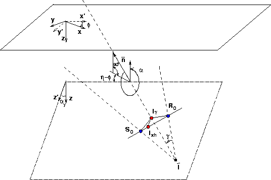
Biondi and Symes (2003) analyze in detail the kinematic
properties of 2-D ADCIGs when the migration velocity is not correct.
Their analysis can be extended to 3-D by following
the same geometrical considerations
we used in the previous sections
to generalize ADCIGs from 2-D to 3-D
(Figure 3).
However,
there is an important conceptual difference
between the 2-D case and the 3-D case.
In 2-D we can assume that
the source and receiver rays cross
even when the data were migrated with the wrong velocity;
below the imaging point in case of too low migration
velocity
and
above the imaging point in the opposite case.
In 3-D, this assumption is easily violated
because two rays are not always coplanar.
Fortunately, the plane-wave interpretation is still valid
and the plane of coplanarity
of Figure 13
is determined
by the coplanarity condition expressed
in equation (10)
applied to the phase vectors of
the incident and reflected plane waves,
or, alternatively
by the coplanarity condition expressed
in equation (18)
applied to the offset dips present in the
prestack image.
The source and receiver plane waves constructively interfere along
an imaging line;
the angle-domain image point ![]() is defined as the intersection of this imaging
line with the tilted plane of coplanarity.
Once this plane is defined,
the geometrical relations
between the objects (rays and imaging points)
that lie on the vertical plane in 2-D
Biondi and Symes (2003),
directly apply to 3-D on the tilted
plane of coplanarity, as it is schematically represented in
Figure 13.
In particular, the relative position
of the angle-domain image point
is defined as the intersection of this imaging
line with the tilted plane of coplanarity.
Once this plane is defined,
the geometrical relations
between the objects (rays and imaging points)
that lie on the vertical plane in 2-D
Biondi and Symes (2003),
directly apply to 3-D on the tilted
plane of coplanarity, as it is schematically represented in
Figure 13.
In particular, the relative position
of the angle-domain image point ![]() and of the crossing point between the source
and receiver ray
and of the crossing point between the source
and receiver ray ![]() are defined on the tilted plane.
The 2-D results translate into the following 3-D results:
are defined on the tilted plane.
The 2-D results translate into the following 3-D results:
| |
(19) |
These results are based on the assumption that the velocity is locally smooth in a neighborhood of the imaging point. Furthermore, the relationship expressed in equation (19) depends on the assumption of stationary raypaths, since we need to invoke Fermat's principle. We can assume stationary raypaths if the velocity perturbations are small. Biondi and Symes (2003) discuss these assumptions in details.
The relationship expressed in equation (19) forms the basis of using ADCIGs for MVA. Similar relationships have been extensively used in MVA methods based on constant-offset Kirchhoff migration Etgen (1990); Meng et al. (1999a,b); Stork (1992). Equation (19) can be directly used to transform measurements of depth errors in ADCIGs into traveltime perturbations that can be inverted by a ray-based tomographic inversion; or it can be the foundation for the derivation of accurate RMO functions to be applied to measure depth errors in ADCIGs.
 |