![\begin{eqnarray}
k_z & = & \sqrt{\frac{\omega^2}{v^2(\bold{s},z)} - \frac{1}{4} ...
...{mx} + k_{hx}\right)^2 + \left( k_{my} + k_{hy}\right)^2
\right]}\end{eqnarray}](img21.gif)
Biondi and Vaillant 2000 discuss the relative accuracy of offset plane-wave migration and CAM for wave-equation imaging. Both are derived from full downward continuation of 3-D prestack data with the Double Square Root (DSR) phase-shift operator:
![\begin{eqnarray}
k_z & = & \sqrt{\frac{\omega^2}{v^2(\bold{s},z)} - \frac{1}{4} ...
...{mx} + k_{hx}\right)^2 + \left( k_{my} + k_{hy}\right)^2
\right]}\end{eqnarray}](img21.gif) |
||
| (10) |
Offset plane wave (OPW) migration Mosher et al. (1997) performs migration of each offset plane wave component of the data independently. It can be interpreted as a reversed-order two-pass prestack migration, where an initial cross-line zero-offset migration is followed by an in-line prestack migration. Another interpretation in that the cross-line offset wavenumber khy in equation (10) is set to zero for downward continuation:
![\begin{eqnarray}
k_z & = & \sqrt{\frac{\omega^2}{v^2(\bold{s},z)} - \frac{1}{4} ...
...1}{4} \left[
\left( k_{mx} + k_{hx}\right)^2 + k_{my}^2
\right]}\end{eqnarray}](img26.gif) |
||
| (11) |
Instead, for CAM, the cross-line offset wavenumber khy is
replaced in equation (10) by its stationary path
![]() given in equation (9):
given in equation (9):
![\begin{eqnarray}
k_z & = & \sqrt{\frac{\omega^2}{v^2(\bold{s},z)} - \frac{1}{4} ...
...+ k_{hx}\right)^2 + \left( k_{my} + \hat k_{hy}\right)^2
\right]}\end{eqnarray}](img28.gif) |
||
| (12) |
Both migrations reduce the full 5-D phase-shift operator to a 4-D operator. In fact, when no multipathing occurs, only a 4-D slice of the 5-D wavefield contributes to the image.
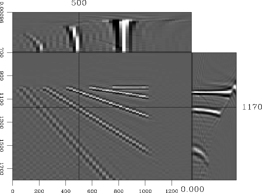
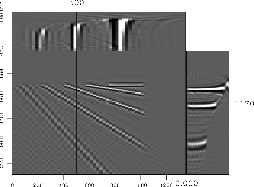
Figures 9 and 10 show
migration results. The final image cube has 4 dimensions, the last
being the common-image gather (CIG) ray parameter axis, generated by
slant stack Prucha et al. (1999). The CIGs are flat for the first
reflectors (dips ![]() ) in both images. For OPW migration,
non-flat gathers start at dip
) in both images. For OPW migration,
non-flat gathers start at dip ![]() , whereas only a dip of
, whereas only a dip of
![]() causes trouble to CAM.
causes trouble to CAM.
 |
 |
In order to have a reference for comparison, we migrated the 4-D common-azimuth data with 5-D phase-shift migration, after zero-padding along a fictitious cross-line offset axis (Figure 8). Figure 11 shows flat gathers even for the most strongly dipping reflectors.
For using the full 5-D phase-shift operator, we added a fictitious cross-line offset axis by zero-padding common-azimuth data. The ``arbitrary'' parameters nhy and dhy are chosen in order to avoid wraparound problems in Fourier Transforms (nhy large enough) and to have the exact value of khy included in our khy range. In practice, we used nhy=24 and dhy=50m.
 |