

Next: Proof of amplitude equivalence
Up: INTRODUCING THE OFFSET CONTINUATION
Previous: Proof of kinematic equivalence
To study the laws of traveltime curve transformation in
the OC process, it is convenient to apply the method of
characteristics Courant (1962) to the eikonal-type equation (5). The
characteristics of (5) (bi-characteristics with respect to
(1)) are the trajectories of the high-frequency energy
propagation in the imaginary OC process. Following the formal analogy
with seismic rays, let's call those trajectories time rays, where
the word time refers to the fact that time rays describe
the traveltime transformation.
According to the theory of first-order partial differential equations,
time rays are determined by a set of ordinary
differential equations (characteristic equations) derived from
(5) :
|  |
|
| (14) |
where Y corresponds to  along a ray, and H corresponds to
  . In this coordinate system, equation (5) takes the form
|  |
(15) |
and serves as an additional constraint for the definition of time rays.
System (14) can be solved by standard mathematical methods. Its
general solution takes the parametric form, where the time
variable tn is the parameter along a time ray:
|  |
(16) |
| (17) |
and C1, C2, and C3 are independent coefficients, constant along each
time ray. To determine the values of these coefficients, we can
pose an initial value
(Cauchy) problem for the system of differential equations (14).
The traveltime curve  for a given common offset h and
the first partial derivative
  along
the same constant offset section provide natural initial conditions for
the Cauchy problem. A particular case of those conditions is the
zero-offset traveltime curve. If the first partial derivative
of traveltime with respect to offset is continuous, it vanishes at
zero offset according to
the reciprocity principle (traveltime must be an even function
of the offset):
 Applying the initial value conditions to the general solution (17)
generates the following expressions for the ray invariants:
|  |
|
| (18) |
Finally, substituting (18) into (17) produces an explicit
parametric form of
the ray trajectories:
|  |
(19) |
Here y1, h1, and t1 are the coordinates of the continued seismic
section. The first of equations (19) indicates that the time
ray projections to a common-offset section
have a parabolic form. Time rays don't exist for  (a locally horizontal reflector), because in this case
post-NMO offset continuation
transform is not required.
The actual parameter that
determines a particular time ray is the reflection point location.
This important conclusion follows from the known parametric equations
|  |
(20) |
where x is the reflection point, u is half of the wave velocity (u=v/2),
tv is the vertical time (reflector depth divided by u), and
 is the
local reflector dip. Taking into account that the derivative of the zero-offset
traveltime curve is
|  |
(21) |
and substituting (20) into (19), we get
|  |
(22) |
where  .
.
To visualize the concept of time rays, let's consider some simple analytic
examples of its application to geometric analysis of
the offset continuation process.
The
simplest and most important example is the case of a plane dipping
reflector. Putting
the origin of the y axis at the reflector plane intersection with the
surface, we can express the reflection traveltime after NMO in the form
|  |
(23) |
where  , and
, and  is the dip angle.
The zero-offset traveltime in this case is a straight line:
|  |
(24) |
According to (19), time rays are defined by
|  |
(25) |
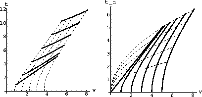
The geometry of the OC transformation is shown in Figure
2.
ocopln
Figure 2 Transformation of
the reflection traveltime curves in the OC process: the case of a plane dipping
reflector. Left: Time coordinate before the NMO correction. Right:
Time coordinate after NMO. Solid lines indicate traveltime curves;
dashed lines, time rays.


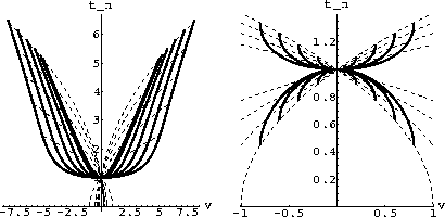
The second example is the case of a point diffractor (the left side of Figure
3).
Without loss of generality, the origin of the midpoint axis can be put
above the
diffraction point. In this case
the zero-offset reflection traveltime curve has the well-known
hyperbolic form
|  |
(26) |
where z is the depth of the diffractor, and u=v/2 is half of the wave
velocity. Time rays are defined according to (19),
as follows:
|  |
(27) |
ococrv
Figure 3 Transformation of
the reflection traveltime curves in the OC process. Left: the case of
a diffraction point.
Right: the case of an elliptic reflector. Solid lines indicate traveltime
curves; dashed lines, time rays.


The third curious example (the right side of Figure 3) is the case
of a focusing
elliptic reflector. Let y be the center of the ellipse
and h be half the distance between the focuses of the ellipse. If both
focuses are on the surface, the zero-offset traveltime curve is defined by the
so-called ``DMO smile'' Deregowski and Rocca (1981):
|  |
(28) |
where  , and z is the small semi-axis of the ellipse.
The time ray equations are
|  |
(29) |
When y1 coincides with y, and h1 coincides with h, the source and the
receiver are in the focuses of the elliptic reflector, and the traveltime curve
degenerates to a point t1=tn. This remarkable fact is the actual
basis of the
geometric theory of dip moveout Deregowski and Rocca (1981).


Next: Proof of amplitude equivalence
Up: INTRODUCING THE OFFSET CONTINUATION
Previous: Proof of kinematic equivalence
Stanford Exploration Project
6/19/2000


 Applying the initial value conditions to the general solution (17)
generates the following expressions for the ray invariants:

 (a locally horizontal reflector), because in this case
post-NMO offset continuation
transform is not required.


 , and
, and 

