

Next: A 2-D example
Up: Popovici : PSPI and
Previous: THE PHASE SHIFT PLUS
Stoffa et al. (1990) present an alternative to the PSPI. Stoffa et al.
replace the
different velocities used in the downward continuation step
with a single
average velocity. A following phase shift of the wavefield with a
perturbation term accounts for lateral velocity variations.
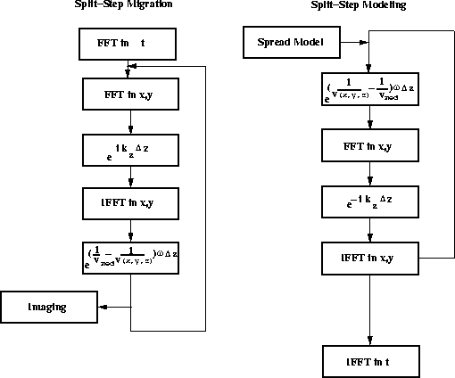
The flow of Stoffa's migration is shown in Figure ![[*]](http://sepwww.stanford.edu/latex2html/cross_ref_motif.gif) .
.
The Split-Step algorithm is based on splitting the space variant
slowness ( ) into a constant term and a perturbation
term,

where s0(z) is a reference slowness defined as the average slowness
in a depth interval.
The wave equation (1) is Fourier transformed along the time
axis to become
|  |
(13) |
After inserting the slowness split into the perturbation term and
the average term the equation is transformed into
| ![\begin{displaymath}
{\partial^2 P(x,z,\omega) \over \partial z^2}+
{\partial^2 P...
...omega^2[2 s_0(z) \Delta s(x,z)+\Delta s^2(x,z)] P(x,z,\omega) .\end{displaymath}](img32.gif) |
(14) |
Defining the right side of the equation (14)

we can write (14) as
|  |
(15) |
which is an inhomogeneous wave equation with a source
term  .
splitboth
Figure 2 Split-Step Fourier migration and the
conjugate transpose Split-Step Fourier modeling algorithm.

Stoffa et al. show that
equation (15) can be integrated over a thin depth layer  by ignoring the contribution of the
  .This is done by Fourier transforming equation (15)
in surface coordinates, dropping the second
order term of the slowness perturbation and subsequently
integrating over the depth layer
  .
After inverse Fourier transforming into surface coordinates the solution
for downward propagating the wavefield has the form
|  |
(16) |
where  represents the wavefield downward continued
with the average slowness s0(z).
For upward continuation we just have to change the sign of
 to have
|  |
(17) |
Though the mathematical path is very different from the one
Gazdag and Sguazzero (1984)
followed, the solution is very similar if you consider the PSPI
algorithm with a single velocity.
The phase addition and subtraction trick in the PSPI algorithm is replaced
by multiplication with
|  |
(18) |
after the downward extrapolation.
Compare the phase shift in equation (18)
with the trick in PSPI modeling to phase shift with

followed by

The only difference is that in PSPI the phase shift
is done after the inverse Fourier transform while in Split-Step it is
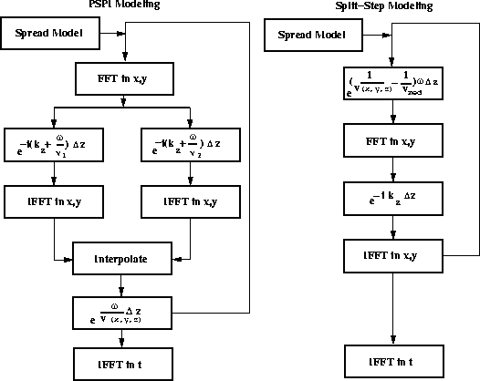
done before the Fourier transform. The two modeling algorithms are compared
in Figure ![[*]](http://sepwww.stanford.edu/latex2html/cross_ref_motif.gif) .
pspisplitmod
.
pspisplitmod
Figure 3 PSPI modeling and Split-Step Fourier modeling.


Next: A 2-D example
Up: Popovici : PSPI and
Previous: THE PHASE SHIFT PLUS
Stanford Exploration Project
11/18/1997
![[*]](http://sepwww.stanford.edu/latex2html/cross_ref_motif.gif) .
.
![]() ) into a constant term and a perturbation
term,
) into a constant term and a perturbation
term,
![]()
![]()

![]() by ignoring the contribution of the
by ignoring the contribution of the ![]() .This is done by Fourier transforming equation (15)
in surface coordinates, dropping the second
order term of the slowness perturbation and subsequently
integrating over the depth layer
.This is done by Fourier transforming equation (15)
in surface coordinates, dropping the second
order term of the slowness perturbation and subsequently
integrating over the depth layer ![]() .
After inverse Fourier transforming into surface coordinates the solution
for downward propagating the wavefield has the form
.
After inverse Fourier transforming into surface coordinates the solution
for downward propagating the wavefield has the form
![]()
![]()
![[*]](http://sepwww.stanford.edu/latex2html/cross_ref_motif.gif) .
.
