


![[*]](http://sepwww.stanford.edu/latex2html/cross_ref_motif.gif) .
First it scans the seismogram array for seismograms that are entirely zero.
These are taken as missing data and the rest of the data as known.
Then it passes over the seismograms sending groups
to subroutine gapatch() .
Each group is characterized by a known seismogram on the left
and on the right, and a collection of unknown seismograms in between.
.
First it scans the seismogram array for seismograms that are entirely zero.
These are taken as missing data and the rest of the data as known.
Then it passes over the seismograms sending groups
to subroutine gapatch() .
Each group is characterized by a known seismogram on the left
and on the right, and a collection of unknown seismograms in between.
# Fill in missing traces by interpolating across gaps on best slopes.
#
subroutine gapfill( data, n1,n2, known    , maxslope)
integer		          n1,n2, known(n2), maxslope,   i1,i2, left, rite, w2
real		    data( n1,n2),		        big
do i2= 1, n2 {
	big = 0.
	do i1= 1, n1
		if( big < abs( data(i1,i2)) )
		    big = abs( data(i1,i2))
	if( big > 0.) { known(i2) = 1 }
	else	      { known(i2) = 0 }
	}					# Even if zero,
  left = 1					# take first trace known.
do rite= 2, n2 {
	if( known( rite) > 0 | rite == n2) {	# Take last trace known.
		w2 = rite - left + 1
		call gapatch( data(1,left), n1, w2, maxslope)
		left = rite
		}
	}
return; end
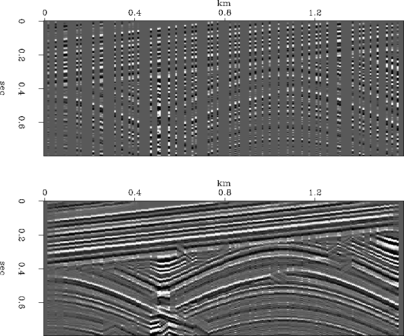
Testing gapfill() on synthetic data gave the result
in Figure 1.
This figure illustrates that the method generally works,
failing mainly where you expect it to,
along the unconformity and at the buried focus
where there is wave triplication.
The input data in this example appears to be irregular.
Actually, it is on a mesh that is more densely sampled
than normal leaving many more gaps than data locations.
In practice, where there is more data than gaps,
an alternate method that assumes imperfect data might be preferable.
I should test it on some field data.
 |


# make patches on 1-axis, each as wide as a gap, length depending on width.
#
subroutine gapatch( data, n1, n2, maxslope )
integer			  n1, n2, maxslope
real		    data( n1, n2)
integer	i1,i2, w1,w2,j1,j2,k1,k2, maxlag, w0
parameter ( w0 = 20)
temporary real	    wind  ( w0+maxslope*(n2-1), n2), dcopy ( n1, n2)
temporary real	    windwt( w0+maxslope*(n2-1), n2), wallwt( n1, n2)
maxlag =  maxslope * (n2-1)
w1 = w0 + maxlag	;  k1 = 1 + (1.25 * n1) / w0
w2 = n2			;  k2 = 1
call zero( n1*n2, wallwt)
call zero( n1*n2, dcopy )
    j2= 1
do  j1= 1, k1 {
	call patch( 0, 0, j1,j2, k1,k2,   data, n1,n2,   wind, w1,w2)
	call gapinside( wind,  w1,w2, windwt, maxslope)
	call patch( 1, 1, j1,j2, k1,k2,  dcopy, n1,n2,   wind, w1,w2)
	call patch( 1, 1, j1,j2, k1,k2, wallwt, n1,n2, windwt, w1,w2)
	}
do i2= 1, n2
do i1= 1, n1
	if(                                      wallwt(i1,i2) != 0.)
		data( i1,i2)  =  dcopy( i1,i2) / wallwt(i1,i2)
return;	end
Subroutine gapatch() takes two seismograms surrounding
a collection of zero seismograms--call this a ``tower'' of data--and
slices the time axis to make ``patches'' of data.
The patches are extracted and put back
with subroutine patch() described
in an accompanying article (page ).
These patches are passed along to subroutine gapinside()
for handling.
It adds data onto the emptiness in the center of the tower
and it also accumulates a weighting function for each patch
from various triangles that taper data
towards the top and bottom of the patch
and taper the data as it is projected into the tower from either side.
The weighting function for each patch typically differs from other
patches (because of the various slopes encountered in each patch).
The patches overlap, and after each one is processed,
they must be reassembled seamlessly.
This is done by accumulating a weighting function of the whole
tower of data at the same time the patches are accumulated.
The final step is to divide the accumulation
by the tower weight (where it is nonzero).
Let us return to the parameter
w0
at the beginning of gapatch() .
Increasing this parameter makes patches taller,
thereby increasing the size of the disturbed zone near the unconformity.
Decreasing this parameter increases the number of false picks,
particularly near the ends of the dip range.
Since the mispicks (not shown) are not uniformly distributed,
but seem to scatter near the extremes of the dip range,
it seems more theoretical work
should go into the analysis of burone() .
The parameter
w0
relates to the patch time duration
in the following way:
At the largest dip there will be the fewest number of time points
correlated across the gap. This number is w0.
I was uncertain whether to base the number k1 of patches on
w0 or on
w1, the patch height.
One seems an over estimate,
the other an under estimate.
I chose the cautious estimate but then cut the overlap factor to 25%.
The actual overlap will be larger where the dips are modest.
Before we look at the messy internals of what happens in each patch,
let us examine the lowest level subroutine burone() .
# residual(a) =  SELFDOT( x(g)-a*y(1) ) +  SELFDOT( y(1)-a*x(g) )
#
subroutine burone( x,   y,n, g, a )
integer                   n, g,          m
real               x(n),y(n),   a,       dot, aa,ra
m = n - g + 1
aa =   dot(m, y(1),y(1)) + dot(m, x(g),x(g)) + 1.e-20
ra =   dot(m, y(1),x(g)) + dot(m, x(g),y(1))
a  =   ra / aa
return; end
This routine is called with two traces, one from each side of the patch. It tests the correlation of the two traces at a specified relative time shift. The correlation is defined by the simultaneous prediction of the left trace from the right and the right trace from the left. If you know the Burg spectral estimation procedure (see FGDP) this is a familiar idea. Requiring the leftward predictor to equal the rightward predictor contributes to imposing the monoplanewave model upon the data. In FGDP p. 135-6 it is proven that the correlation coefficient computed this way has a magnitude that is always less than unity. Notice that burone()
presumes that the left seismogram
x(n) carries its information
later
than the right seismogram y(n).
Since in practice either one could be later,
it is necessary to call
burone() twice, the second time with seismograms interchanged.
# Figure which direction works the best, then interpolate along it.
#
subroutine gapinside( data, n1,n2,  wiwt, maxslope )
integer			    n1,n2,        maxslope,  i1,i2
real		      data( n1,n2), wiwt(n1,n2),     aa, bb, coh, w, tri
integer                                          m, j1, lag,lagl,lagr, mid,best
temporary real	coherency( 1+2*maxslope*(n2-1))
call zero(                  n1*n2,  wiwt )
mid  = 1 +  maxslope * (n2-1)
do lag = 1, mid {
	call burone( data,      data(1,n2),n1, lag, coherency( mid+lag-1) )
	call burone( data(1,n2),data,      n1, lag, coherency( mid-lag+1) )
	}
best = mid
do lag = 1, 2*mid-1
	if(  coherency( best) < coherency(lag) )
	                best  =           lag
coh = amax1( coherency( best), 0.);	lag =  1 + iabs( mid - best)
do i2= 2, n2-1 {
	aa = (n2-i2) / float( n2-1);	lagr =  1.5 + (lag-1) * aa
	bb = (i2- 1) / float( n2-1);	lagl =  1.5 + (lag-1) * bb
	if( best < mid ) {
		m= n1-lagl+1;  do i1= 1,m {  j1= i1+lagl-1;       w= tri(i1,m)
			data(j1,i2)= data(j1,i2) + data(i1,  1) * w * aa * coh
			wiwt(j1,i2)= wiwt(j1,i2) +                w * aa
			}
		m= n1-lagr+1;  do i1= 1,m {  j1= i1+lagr-1;       w= tri(i1,m)
			data(i1,i2)= data(i1,i2) + data(j1, n2) * w * bb * coh
			wiwt(i1,i2)= wiwt(i1,i2) +                w * bb
			}
		}
	else {	m= n1-lagl+1;  do i1= 1,m {  j1= i1+lagl-1;       w= tri(i1,m)
			data(i1,i2)= data(i1,i2) + data(j1,  1) * w * bb * coh
			wiwt(i1,i2)= wiwt(i1,i2) +                w * bb
			}
		m= n1-lagr+1;  do i1= 1,m {  j1= i1+lagr-1;       w= tri(i1,m)
			data(j1,i2)= data(j1,i2) + data(i1, n2) * w * aa * coh
			wiwt(j1,i2)= wiwt(j1,i2) +                w * aa
			}
		}
	}
return; end
Subroutine gapinside() first
calls burone() twice, once for each allowable lag.
Then it finds the lag with the best coherence
and uses that to set the dip.
We can imagine the coherence between the two observed traces
decaying steadily from one towards the other.
Instead of attempting to allow for such a coherence model,
I simply scaled all signals in the gap by the coherence
measured across the gap.
Finally is a sequence of four loops
that I find very confusing.
Two are needed because the lag may be positive or negative.
Two are needed because information is projected from
each seismogram toward the other.
This projection is under a linear taper
and there is an additional triangle taper on the time axis
applied by the function tri() .
# Triangle function (isoceles)
#
real function tri( i, n)
integer            i, n
real mid, wide, x
mid  = (n+1)/2.;
wide =   n /2.
x    =   abs( (i-mid) / wide )
tri  =  1. - abs( x)
return; end