As demonstrated in Rickett and Sava (2002), ADCIGs suffer from poor sampling of the source or receiver wavefield. This effect is not very obvious from the derivation in Sava and Fomel (2003); it is, however, more evident from the perspective of shot-profile migration. Appendix A analytically demonstrates that in locally constant-velocity media, when the receiver wavefield is densely sampled, the circular wavefronts of the downward continued receiver wavefields can be well reconstructed; hence the multi-offset imaging condition in equation (1) produces a linear relationship between subsurface half offset hx and depth z for a specific CMP location x as follows:
| |
(4) |
| |
(5) |
Let us consider the extreme case for poor sampling, where we have only one receiver. As demonstrated in Appendix B, when we have only one shot and one receiver, the multi-offset imaging condition in equation (1) no longer produces a linear relationship between subsurface half offset hx and depth z. Instead z and hx are non-linearly related as follows:
| |
(6) |
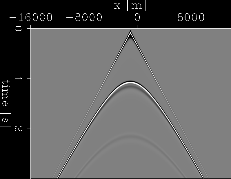
For example, Figure ![[*]](http://sepwww.stanford.edu/latex2html/cross_ref_motif.gif) shows a synthetic shot gather for a flat reflector at z=2000 meters, with a constant velocity v=4000 m/s.
The shot is located at x=-1000 meters. For an image point at x=0 meter, z=2000 meters, the reflection angle should
be
shows a synthetic shot gather for a flat reflector at z=2000 meters, with a constant velocity v=4000 m/s.
The shot is located at x=-1000 meters. For an image point at x=0 meter, z=2000 meters, the reflection angle should
be ![]() . Figure
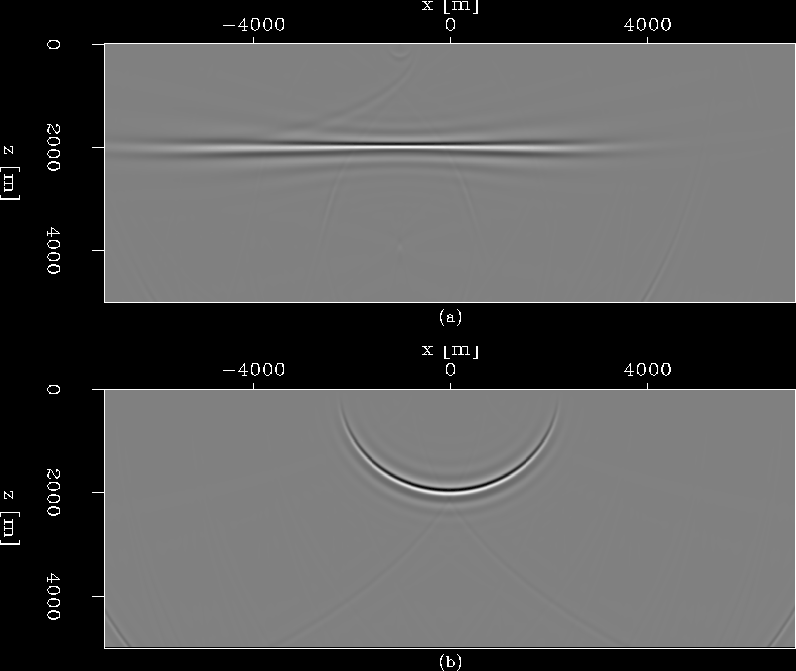
. Figure ![[*]](http://sepwww.stanford.edu/latex2html/cross_ref_motif.gif) (a) shows the migrated image obtained by using all the receivers shown in
Figure
(a) shows the migrated image obtained by using all the receivers shown in
Figure ![[*]](http://sepwww.stanford.edu/latex2html/cross_ref_motif.gif) .
Figure
.
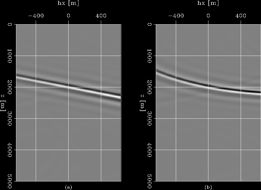
Figure ![[*]](http://sepwww.stanford.edu/latex2html/cross_ref_motif.gif) (a) shows the SODCIG for surface location x=0 meter; it shows a perfectly straight line intersecting
at (0,2000) in the subsurface-offset domain (hx, z). Figure
(a) shows the SODCIG for surface location x=0 meter; it shows a perfectly straight line intersecting
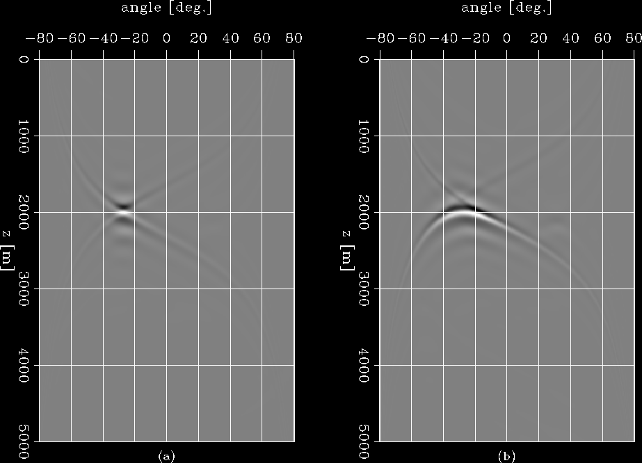
at (0,2000) in the subsurface-offset domain (hx, z). Figure ![[*]](http://sepwww.stanford.edu/latex2html/cross_ref_motif.gif) (a) shows
the ADCIG obtained by slant-stacking the corresponding SODCIGs in
Figure
(a) shows
the ADCIG obtained by slant-stacking the corresponding SODCIGs in
Figure ![[*]](http://sepwww.stanford.edu/latex2html/cross_ref_motif.gif) (a). This result also shows a point located at about
(a). This result also shows a point located at about ![]() , which matches the theoretical result well.
Figure
, which matches the theoretical result well.
Figure ![[*]](http://sepwww.stanford.edu/latex2html/cross_ref_motif.gif) (b), in contrast, shows the migration result obtained by using only one receiver located at x=1000 meters.
The image is an ellipse, which is basically a prestack impulse response. The SODCIG at x=0 meter is shown in Figure
(b), in contrast, shows the migration result obtained by using only one receiver located at x=1000 meters.
The image is an ellipse, which is basically a prestack impulse response. The SODCIG at x=0 meter is shown in Figure ![[*]](http://sepwww.stanford.edu/latex2html/cross_ref_motif.gif) (b),
and as predicted by equation (6), it is a circle instead of a straight line in the subsurface-offset domain.
The corresponding ADCIG is shown in Figure
(b),
and as predicted by equation (6), it is a circle instead of a straight line in the subsurface-offset domain.
The corresponding ADCIG is shown in Figure ![[*]](http://sepwww.stanford.edu/latex2html/cross_ref_motif.gif) (b). Instead of a nicely focused point at
(b). Instead of a nicely focused point at ![]() ,
we can identify a downward-frowning curve.
,
we can identify a downward-frowning curve.
|
flat.shot
Figure 1 Synthetic shot gather for a flat reflector where the shot is located at x=-1000 meters. The modeling is done using finite difference. |  |
|
flat.img
Figure 2 Migration results for only one shot. Panel (a) shows the migrated image for all the receivers shown in Figure ![[*]](http://sepwww.stanford.edu/latex2html/cross_ref_motif.gif) ,
while (b) shows the migrated image for only one receiver located at x=1000 meters. ,
while (b) shows the migrated image for only one receiver located at x=1000 meters.
|  |
|
flat.sodcig
Figure 3 SODCIGs at x=0 meter for different results. (a) SODCIG extracted from the result in Figure ![[*]](http://sepwww.stanford.edu/latex2html/cross_ref_motif.gif) (a), where
a straight line is obtained, since the receiver wavefield is well sampled.
(b) SODCIG extracted from the result in Figure (a), where
a straight line is obtained, since the receiver wavefield is well sampled.
(b) SODCIG extracted from the result in Figure ![[*]](http://sepwww.stanford.edu/latex2html/cross_ref_motif.gif) (b), where
a circle instead of a straight line is obtained, since the wavefield is extremely poorly sampled. (b), where
a circle instead of a straight line is obtained, since the wavefield is extremely poorly sampled.
|  |
|
flat.adcig
Figure 4 ADCIGs at x=0 for different results. (a) ADCIG computed from Figure ![[*]](http://sepwww.stanford.edu/latex2html/cross_ref_motif.gif) (a),
where a nicely focused point at (a),
where a nicely focused point at ![[*]](http://sepwww.stanford.edu/latex2html/cross_ref_motif.gif) (a) is linear.
(b) ADCIG computed from Figure (a) is linear.
(b) ADCIG computed from Figure ![[*]](http://sepwww.stanford.edu/latex2html/cross_ref_motif.gif) (b),
where a downward-frowning curve instead of a point is obtained,
because the local-offset gather in (b),
where a downward-frowning curve instead of a point is obtained,
because the local-offset gather in ![[*]](http://sepwww.stanford.edu/latex2html/cross_ref_motif.gif) (b) is non-linear. (b) is non-linear.
|  |