

Next: SEG-EAGE salt data set
Up: Biondi: Narrow-azimuth migration
Previous: Coplanarity condition
We can gain a intuitive understanding of the
effects of applying the coplanarity condition,
and of the trade-off when setting the parameters
for narrow-azimuth migration,
by analyzing the results of two full source-receiver migrations of the
synthetic data set with five dipping planes,
which we introduced in the previous section.
I used 8 cross-line offsets
for both migrations;
for the first migration
the cross-line sampling was 100 meters
whereas for the second one
the cross-line sampling was 50 meters.
There is a trade-off between the coarser and finer cross-line
offset sampling.
With the finer sampling we expect stronger artifacts caused
by the circular boundary condition because the offset range is narrower
(only 400 meters vs. 800 meters).
On the other hand,
with the finer offset sampling
the cross-line dip range is wider
than with the coarse offset sampling
and thus we expect better imaging of the events
reflected with wide-aperture angles
from the steeply dipping planes.
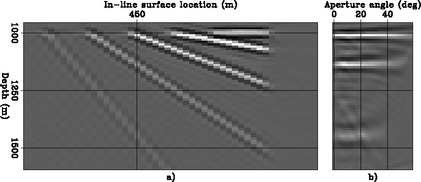
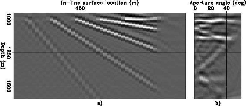
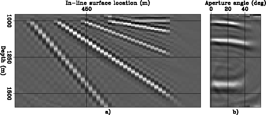
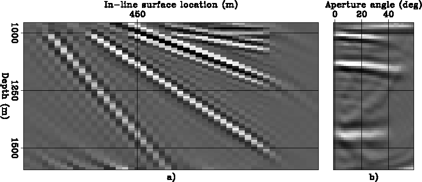
These ``theoretical'' predictions are confirmed by
the zero offset images (panels a) and
the ADCIGs (panels b) displayed in
Figure ![[*]](http://sepwww.stanford.edu/latex2html/cross_ref_motif.gif) (
( meters)
and
Figure
 ![[*]](http://sepwww.stanford.edu/latex2html/cross_ref_motif.gif) (
( meters).
The ADCIG shown in Figure
 ![[*]](http://sepwww.stanford.edu/latex2html/cross_ref_motif.gif) b
shows stronger artifacts
than the ADCIG shown in Figure
b
shows stronger artifacts
than the ADCIG shown in Figure ![[*]](http://sepwww.stanford.edu/latex2html/cross_ref_motif.gif) b.
Even the ```stacked'' image
(i.e. zero-offset image) shown
in Figure
b.
Even the ```stacked'' image
(i.e. zero-offset image) shown
in Figure ![[*]](http://sepwww.stanford.edu/latex2html/cross_ref_motif.gif) a
has strong artifacts, at least in the shallow part of
the section.
On the other hand, the finer offset sampling
allows a slight better imaging of the wide-aperture reflection
from the 60-degree plane,
as the comparison of the deepest event
in Figure
a
has strong artifacts, at least in the shallow part of
the section.
On the other hand, the finer offset sampling
allows a slight better imaging of the wide-aperture reflection
from the 60-degree plane,
as the comparison of the deepest event
in Figure ![[*]](http://sepwww.stanford.edu/latex2html/cross_ref_motif.gif) b
and Figure
b
and Figure ![[*]](http://sepwww.stanford.edu/latex2html/cross_ref_motif.gif) b
demonstrates.
b
demonstrates.
stack-cig-azim-hy0-data1
Figure 5
(a) Stack (i.e. image at zero offset) and (b) CIG produced by full prestack migration
with Nyh=8 and  meters.


stack-cig-azim-hy0-data2
Figure 6
(a) Stack (i.e. image at zero offset) and (b) CIG produced by full prestack migration
with Nyh=8 and  meters.


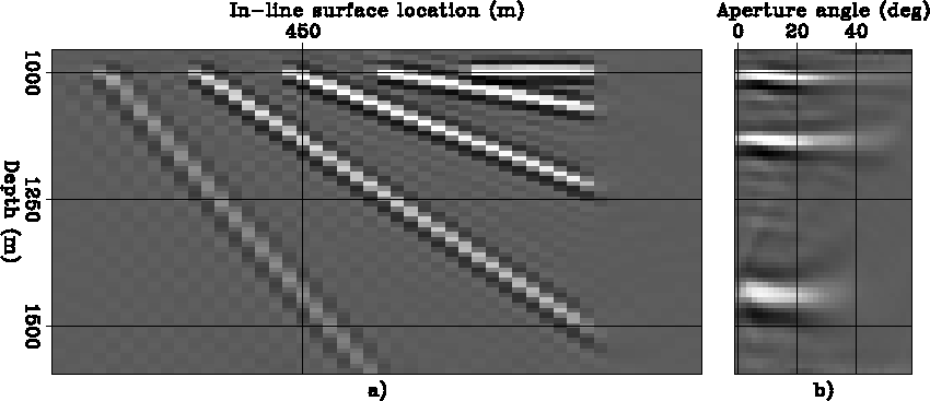
Figure ![[*]](http://sepwww.stanford.edu/latex2html/cross_ref_motif.gif) shows the same section and ADCIG
as in Figure
shows the same section and ADCIG
as in Figure ![[*]](http://sepwww.stanford.edu/latex2html/cross_ref_motif.gif) but after applying the coplanarity condition
for zero azimuth (i.e.
but after applying the coplanarity condition
for zero azimuth (i.e.  =0).
As expected, the events from the flattish
reflectors are preserved since their azimuth at the reflection
point is close to zero.
In contrast, the reflections from the steeper reflectors are
attenuated because their azimuth at the reflection
point is larger than zero.
An interesting side-benefit of the capability of selecting
reflections with a given azimuthal direction
from full prestack migration,
is the possibility to demonstrate the differences
between the zero azimuth image
shown in Figure ![[*]](http://sepwww.stanford.edu/latex2html/cross_ref_motif.gif) ,
and the result obtained by common-azimuth migration
shown in Figure
,
and the result obtained by common-azimuth migration
shown in Figure ![[*]](http://sepwww.stanford.edu/latex2html/cross_ref_motif.gif) .
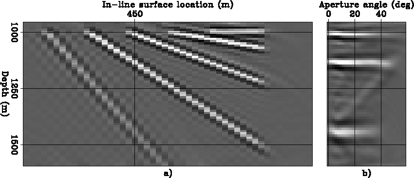
In constant velocity,
the image produced
by common-azimuth migration
is equivalent to the zero-azimuth image.
However, in variable velocity the two images
are substantially different.
The zero azimuth image
(Figure
.
In constant velocity,
the image produced
by common-azimuth migration
is equivalent to the zero-azimuth image.
However, in variable velocity the two images
are substantially different.
The zero azimuth image
(Figure ![[*]](http://sepwww.stanford.edu/latex2html/cross_ref_motif.gif) )
contains only the events that were
close to zero azimuth at the reflection point.
In contrast,
the common-azimuth migration image
(Figure
)
contains only the events that were
close to zero azimuth at the reflection point.
In contrast,
the common-azimuth migration image
(Figure ![[*]](http://sepwww.stanford.edu/latex2html/cross_ref_motif.gif) )
contains all the events.
Common-azimuth downward continuation propagates all the events
assuming that they are coplanar along the zero azimuth.
In variable velocity this assumption is incorrect for some of the events,
which are therefore slightly mispositioned in the image.
)
contains all the events.
Common-azimuth downward continuation propagates all the events
assuming that they are coplanar along the zero azimuth.
In variable velocity this assumption is incorrect for some of the events,
which are therefore slightly mispositioned in the image.
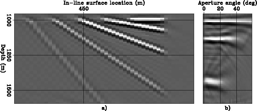
stack-cig-azim0-data1
Figure 7
(a) Stack (i.e. image at zero offset) and (b) CIG for reflections with
0 degrees azimuth at the image point.
This image cube was produced starting from the image cube
obtained by full prestack migration
with Nyh=8 and  meters.


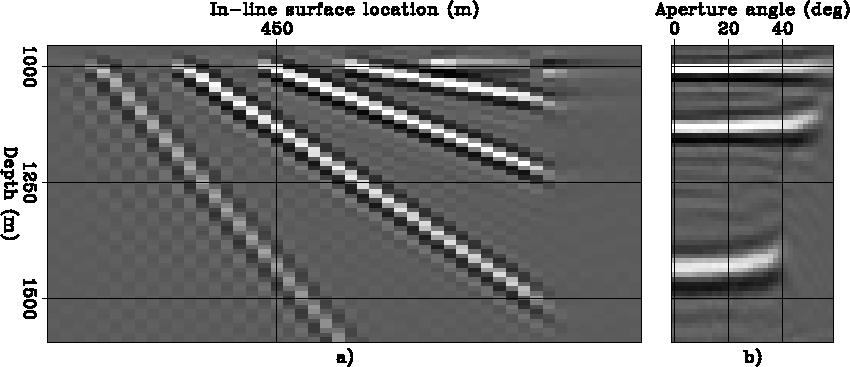
stack-cig-azim-comaz
Figure 8
(a) Stack (i.e. image at zero offset) and (b) CIG produced by common-azimuth migration.


As the common-azimuth migration image illustrates,
the challenge of this data set is to image properly
the wide-aperture reflections from the 60-degree plane.
Simple ray-tracing modeling indicates that those reflections
occur along an azimuth oriented approximately at 18 degrees
with respect to the acquisition geometry.
Figure ![[*]](http://sepwww.stanford.edu/latex2html/cross_ref_motif.gif) shows the image obtained by selecting the reflections with 18-degrees azimuth
from the results of full prestack
migration with the coarser offset sampling
(
shows the image obtained by selecting the reflections with 18-degrees azimuth
from the results of full prestack
migration with the coarser offset sampling
( meters).
Figure
 ![[*]](http://sepwww.stanford.edu/latex2html/cross_ref_motif.gif) shows the image obtained by selecting the reflections with 18-degrees azimuth
from the results of full prestack
migration with the finer offset sampling
(
shows the image obtained by selecting the reflections with 18-degrees azimuth
from the results of full prestack
migration with the finer offset sampling
( meters).
Both images show significantly weaker artifacts
than the corresponding images with full azimuth
(Figure
 ![[*]](http://sepwww.stanford.edu/latex2html/cross_ref_motif.gif) and
Figure
and
Figure ![[*]](http://sepwww.stanford.edu/latex2html/cross_ref_motif.gif) ).
Figure
).
Figure ![[*]](http://sepwww.stanford.edu/latex2html/cross_ref_motif.gif) has weaker artifacts than
Figure
has weaker artifacts than
Figure ![[*]](http://sepwww.stanford.edu/latex2html/cross_ref_motif.gif) .
The reflections for
the 60-degree plane is flat as a function
of the reflection angle for both ADCIGs (panels b),
but Figure
.
The reflections for
the 60-degree plane is flat as a function
of the reflection angle for both ADCIGs (panels b),
but Figure ![[*]](http://sepwww.stanford.edu/latex2html/cross_ref_motif.gif) b
has broader angular bandwidth
(up to 40 degrees for as compared with up to 35 degrees)
than Figure
b
has broader angular bandwidth
(up to 40 degrees for as compared with up to 35 degrees)
than Figure ![[*]](http://sepwww.stanford.edu/latex2html/cross_ref_motif.gif) b.
b.
stack-cig-azim18-data1
Figure 9
(a) Stack (i.e. image at zero offset) and (b) CIG for reflections with
18 degrees azimuth at the image point.
This image cube was produced starting from the image cube
obtained by full prestack migration
with Nyh=8 and  meters.


stack-cig-azim18-data2
Figure 10
(a) Stack (i.e. image at zero offset) and (b) CIG for reflections with
18 degrees azimuth at the image point.
This image cube was produced starting from the image cube
obtained by full prestack migration
with Nyh=8 and  meters.


The best-quality image
can be obtained by stacking the images corresponding to
a range of azimuths.
This range can be fairly narrow
because of the narrow-azimuth nature of streamer data.
In this example, I stacked the image corresponding to azimuths
within the 0-30 degrees range.
Figure ![[*]](http://sepwww.stanford.edu/latex2html/cross_ref_motif.gif) and
Figure
and
Figure ![[*]](http://sepwww.stanford.edu/latex2html/cross_ref_motif.gif) are the result of this averaging process.
Notice the further attenuation of
the artifacts as compared with both the full-azimuth
images
(Figure
are the result of this averaging process.
Notice the further attenuation of
the artifacts as compared with both the full-azimuth
images
(Figure ![[*]](http://sepwww.stanford.edu/latex2html/cross_ref_motif.gif) and
Figure
and
Figure ![[*]](http://sepwww.stanford.edu/latex2html/cross_ref_motif.gif) )
and the 18-degrees azimuth images
(Figure
)
and the 18-degrees azimuth images
(Figure ![[*]](http://sepwww.stanford.edu/latex2html/cross_ref_motif.gif) and
Figure
and
Figure ![[*]](http://sepwww.stanford.edu/latex2html/cross_ref_motif.gif) ).
As before,
there is a trade-off between
the better signal-to-noise in
Figure
).
As before,
there is a trade-off between
the better signal-to-noise in
Figure ![[*]](http://sepwww.stanford.edu/latex2html/cross_ref_motif.gif) ,
and the wider angular bandwidth in
Figure
,
and the wider angular bandwidth in
Figure ![[*]](http://sepwww.stanford.edu/latex2html/cross_ref_motif.gif) .
.
The last two figures show
that the stacking over azimuth decreases the
amplitude of the reflections with wide reflection angles
relatively to the narrow reflection angles.
The intuitive explanation of this phenomenon
is that the narrow reflection angles are enhanced by
the stacking over azimuth
because they are more stationary as a function of azimuth
than the wide reflection angles.
I believe that this effect can be compensated by applying
an appropriate jacobian during the integration
over azimuth,
but I have not derived such a factor yet.
stack-cig-azim-0-30-data1
Figure 11
(a) Stack (i.e. image at zero offset) and (b) CIG for reflections with
azimuth within the 0-30 degrees range.
This image cube was produced starting from the image cube
obtained by full prestack migration
with Nyh=8 and  meters.


stack-cig-azim-0-30-data2
Figure 12
(a) Stack (i.e. image at zero offset) and (b) CIG for reflections with
azimuth within the 0-30 degrees range.
This image cube was produced starting from the image cube
obtained by full prestack migration
with Nyh=8 and  meters.


Next: SEG-EAGE salt data set
Up: Biondi: Narrow-azimuth migration
Previous: Coplanarity condition
Stanford Exploration Project
7/8/2003
![[*]](http://sepwww.stanford.edu/latex2html/cross_ref_motif.gif) (
(![[*]](http://sepwww.stanford.edu/latex2html/cross_ref_motif.gif) (
(![[*]](http://sepwww.stanford.edu/latex2html/cross_ref_motif.gif) b
shows stronger artifacts
than the ADCIG shown in Figure
b
shows stronger artifacts
than the ADCIG shown in Figure ![[*]](http://sepwww.stanford.edu/latex2html/cross_ref_motif.gif) b.
Even the ```stacked'' image
(i.e. zero-offset image) shown
in Figure
b.
Even the ```stacked'' image
(i.e. zero-offset image) shown
in Figure ![[*]](http://sepwww.stanford.edu/latex2html/cross_ref_motif.gif) a
has strong artifacts, at least in the shallow part of
the section.
On the other hand, the finer offset sampling
allows a slight better imaging of the wide-aperture reflection
from the 60-degree plane,
as the comparison of the deepest event
in Figure
a
has strong artifacts, at least in the shallow part of
the section.
On the other hand, the finer offset sampling
allows a slight better imaging of the wide-aperture reflection
from the 60-degree plane,
as the comparison of the deepest event
in Figure ![[*]](http://sepwww.stanford.edu/latex2html/cross_ref_motif.gif) b
and Figure
b
and Figure ![[*]](http://sepwww.stanford.edu/latex2html/cross_ref_motif.gif) b
demonstrates.
b
demonstrates.
