

Next: REFERENCES
Up: Biondi: Narrow-azimuth migration
Previous: Five-planes synthetic data set
The improvement in image quality achieved by applying
source-receiver migration on a narrow range of cross-line offsets
in conjunction with the coplanarity condition
is demonstrated in the following results obtained
from the SEG-EAGE salt data set.
Figure ![[*]](http://sepwww.stanford.edu/latex2html/cross_ref_motif.gif) a shows the in-line section
of the velocity model taken at cross-line location of 5,770 meters.
Figure
a shows the in-line section
of the velocity model taken at cross-line location of 5,770 meters.
Figure ![[*]](http://sepwww.stanford.edu/latex2html/cross_ref_motif.gif) b shows the corresponding
migrated image obtained by common-azimuth migration.
The section is well imaged everywhere,
with the exception of the bottom of the salt
around in-line location of 4,000 meters.
This inaccuracy in the image is likely to be caused
by the common-azimuth approximation.
b shows the corresponding
migrated image obtained by common-azimuth migration.
The section is well imaged everywhere,
with the exception of the bottom of the salt
around in-line location of 4,000 meters.
This inaccuracy in the image is likely to be caused
by the common-azimuth approximation.
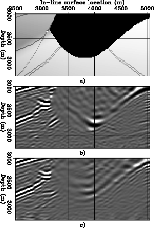
Figure ![[*]](http://sepwww.stanford.edu/latex2html/cross_ref_motif.gif) compares the results
of common-azimuth migration and full source-receiver migration
with 8 cross-line offsets and the application
of the coplanarity condition.
It shows three zooms into the area of interest.
Figure
compares the results
of common-azimuth migration and full source-receiver migration
with 8 cross-line offsets and the application
of the coplanarity condition.
It shows three zooms into the area of interest.
Figure ![[*]](http://sepwww.stanford.edu/latex2html/cross_ref_motif.gif) a shows the velocity model.
Figure
a shows the velocity model.
Figure ![[*]](http://sepwww.stanford.edu/latex2html/cross_ref_motif.gif) b shows the image obtained
by common-azimuth migration.
Figure
b shows the image obtained
by common-azimuth migration.
Figure ![[*]](http://sepwww.stanford.edu/latex2html/cross_ref_motif.gif) c shows the result of
stacking the images obtained by applying the coplanarity condition
on the azimuthal range defined by
c shows the result of
stacking the images obtained by applying the coplanarity condition
on the azimuthal range defined by  degrees.
Notice the improved definition of the bottom of the salt
in Figure
 ![[*]](http://sepwww.stanford.edu/latex2html/cross_ref_motif.gif) c compared
to Figure
c compared
to Figure ![[*]](http://sepwww.stanford.edu/latex2html/cross_ref_motif.gif) b.
b.
Similar improvements are visible in the corresponding depth slices.
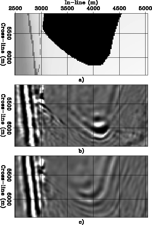
Figure ![[*]](http://sepwww.stanford.edu/latex2html/cross_ref_motif.gif) compares the slices
taken at a depth of 2,600 meters.
Figure
compares the slices
taken at a depth of 2,600 meters.
Figure ![[*]](http://sepwww.stanford.edu/latex2html/cross_ref_motif.gif) a shows the velocity model.
Figure
a shows the velocity model.
Figure ![[*]](http://sepwww.stanford.edu/latex2html/cross_ref_motif.gif) b shows the image obtained
by common-azimuth migration.
Figure
b shows the image obtained
by common-azimuth migration.
Figure ![[*]](http://sepwww.stanford.edu/latex2html/cross_ref_motif.gif) c shows the result of
stacking the images obtained by applying the coplanarity condition
on the azimuthal range defined by
c shows the result of
stacking the images obtained by applying the coplanarity condition
on the azimuthal range defined by  degrees.
Now the salt bottom boundary
located between in-line locations of 4,000 and 4,500 meters is well defined.
Notice that the portion of the salt boundary
that is not well delineated by the image
(between in-line locations of 3,000 and 3,500 meters)
is not properly illuminated by the data.
both-sec-y5770
Figure 13
In-line sections (ym=5,770 m):
(a) the velocity model,
(b) common-azimuth migration.
|
|  |


all-y5770
Figure 14
Zooms of the in-line sections (ym=5,770 m):
(a) the velocity model
(b) common-azimuth migration,
(c) full source-receiver migration with 8 cross-line offsets and
the application of the coplanarity condition.
|
|  |


all-z2600
Figure 15
Zooms of the depth slices (z=2,600 m):
(a) the velocity model
(b) common-azimuth migration,
(c) full source-receiver migration with 8 cross-line offsets and
the application of the coplanarity condition.
|
|  |


I presented a ``narrow-azimuth'' generalization of common-azimuth
migration that overcomes the accuracy limitations
and retains the computational efficiency of the original method.
The new method is based on:
1) the definition of an ``optimal'' range of
cross-line offset dips for the downward continuation,
and 2) application of a ``coplanarity'' condition on the prestack image
for enhancing the correctly focused events.
The migration examples show that the new method has the potential of
correcting the inaccuracy introduced by common-azimuth migration
even in challenging situations such as the one
presented by the SEG-EAGE salt data set.
I would like to thank Bob Clapp and Paul Sava for developing the WEI library
that allowed me to run wave-equation prestack migration using MPI.
Without WEI I could not have tested narrow-azimuth migration on the SEG-EAGE
data set.


Next: REFERENCES
Up: Biondi: Narrow-azimuth migration
Previous: Five-planes synthetic data set
Stanford Exploration Project
7/8/2003
![[*]](http://sepwww.stanford.edu/latex2html/cross_ref_motif.gif) compares the results
of common-azimuth migration and full source-receiver migration
with 8 cross-line offsets and the application
of the coplanarity condition.
It shows three zooms into the area of interest.
Figure
compares the results
of common-azimuth migration and full source-receiver migration
with 8 cross-line offsets and the application
of the coplanarity condition.
It shows three zooms into the area of interest.
Figure ![[*]](http://sepwww.stanford.edu/latex2html/cross_ref_motif.gif) a shows the velocity model.
Figure
a shows the velocity model.
Figure ![[*]](http://sepwww.stanford.edu/latex2html/cross_ref_motif.gif) b shows the image obtained
by common-azimuth migration.
Figure
b shows the image obtained
by common-azimuth migration.
Figure ![[*]](http://sepwww.stanford.edu/latex2html/cross_ref_motif.gif) c shows the result of
stacking the images obtained by applying the coplanarity condition
on the azimuthal range defined by
c shows the result of
stacking the images obtained by applying the coplanarity condition
on the azimuthal range defined by ![[*]](http://sepwww.stanford.edu/latex2html/cross_ref_motif.gif) c compared
to Figure
c compared
to Figure ![[*]](http://sepwww.stanford.edu/latex2html/cross_ref_motif.gif) b.
b.


