


To test the steering methodology versus a more tradition isotropic smoothing approach we created a synthetic velocity model with four reflectors (Figure 3). To simulate picked traveltimes we shot rays through the correct model using a paraxial ray tracing code Rekdal and Biondi (1994) and found ray pairs where Snell's Law was obeyed at the reflectors.
|
overlay-vel-cor
Figure 3 Initial model with reflectors superimposed. | 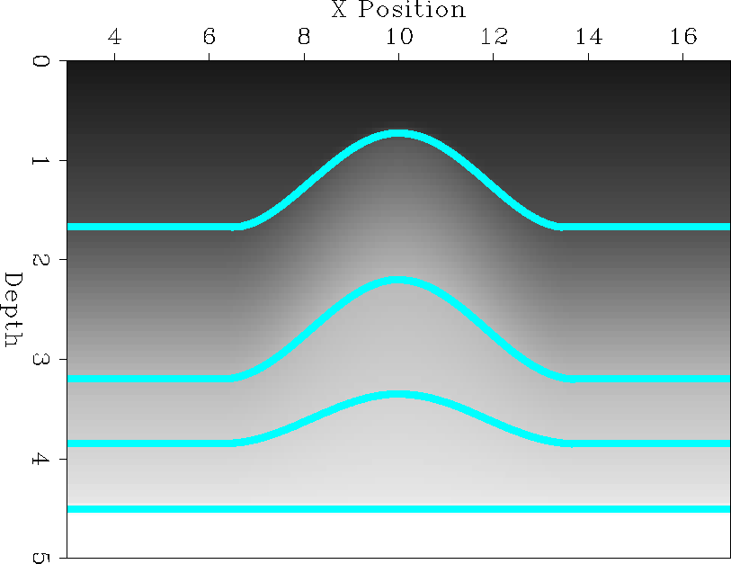 |


|
rays-vel0
Figure 4 Starting model and reflector position with model rays superimposed. | 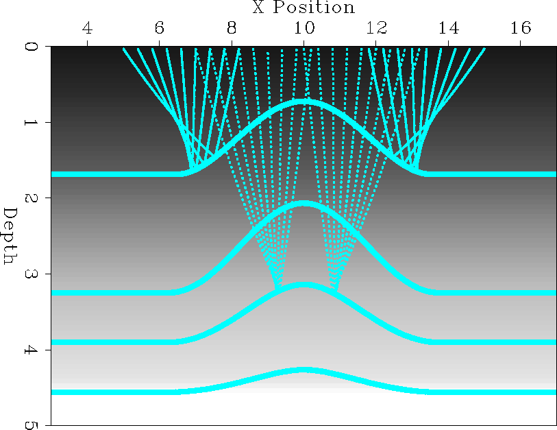 |
We use as our starting guess a v(z) velocity model calculated by averaging over x at each depth. We map migrated the correct depth surfaces according to our initial guess at the velocity model to obtain our first guess at their position (Figure 4). We then shot and matched rays using the initial model and map-migrated reflector position. The difference between the modeled reflection times and the correct reflection times (Figure 5) was then used as input to our tomography problem fitting goals (6).
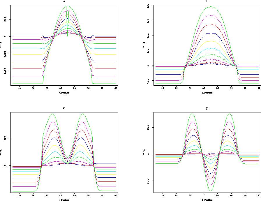 |
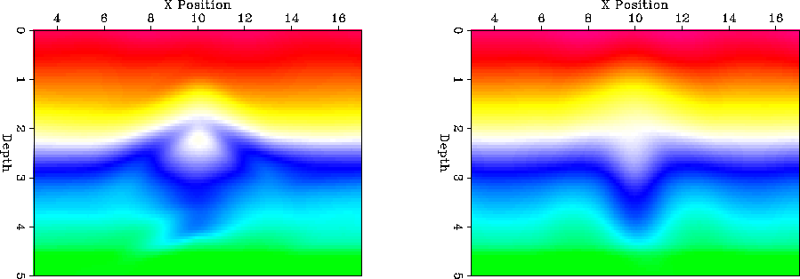
We performed two non-linear iterations of tomography using both the inverse Laplacian and steering filters, oriented along the map migrated reflector position (Figure 6), as our preconditioner. As Figure 7 shows, the Laplacian model estimate has already produced an unwanted isotropic anomaly to explain the w-shaped pattern in the time differentials of reflector 3 and 4 (Figure 5). On the other hand, the steering filter preconditioned result has introduced velocity perturbations that follow our reflector geometry.
|
angles
Figure 6 Angle (from horizontal) of the steering filters. | 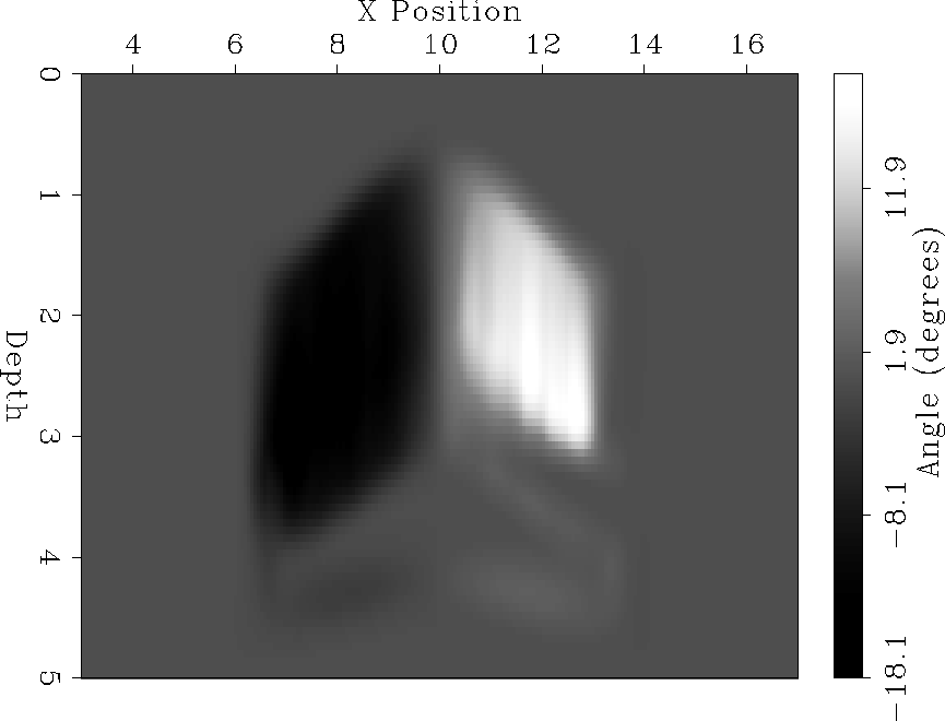 |
To test whether or not the steering filter approach would eventually fall into the same trap as the Laplacian preconditioned scheme we performed two more non-linear iterations. Figure 8 shows the results of all four non-linear iterations using the steering filters. Note how the dome like shape is developing with successive iterations and the low velocity doublet (at 3 km depth and approximately at x=10 km) is diminishing.
 |