


Another reason to account for the amplitudes is
to take advantage of the extra information contained in
the differences of the expected amplitudes of the noise and signal.
Much noise originates from the surface and will either be of constant
amplitude or weaken at a slower rate than does the signal.
For example, in chapter ![[*]](http://sepwww.stanford.edu/latex2html/cross_ref_motif.gif) the noise is expected to be of constant amplitude,
whereas the signal is expected to weaken as t2,
where t is sample time.
the noise is expected to be of constant amplitude,
whereas the signal is expected to weaken as t2,
where t is sample time.
One method of accounting for the weakening of the signal would
be to gain the input by t2,
but this would strengthen the noise at depth.
A better method would be to account for the amplitude differences
in the inversion itself.
These amplitude differences may be taken advantage of by using them
as part of the characterization of the signal and noise.
As an example,
suppose the noise amplitude falls off as t and the signal amplitude
falls off as t2.
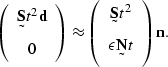
Systems () and () may be modified to become
| |
(56) |
| |
(57) |
) becomes
 |
(58) |
) are in fact
matrices that have the values of t and t2 along the diagonal
that correspond
to the time values of the samples of
Notice that the assumption of stationarity for ![]() and
and ![]() has
been violated somewhat by the time scaling.
This is not necessarily a problem since the filters
has
been violated somewhat by the time scaling.
This is not necessarily a problem since the filters ![]() and
and ![]() involve only the spectrum of the signal and noise.
This spectrum could be assumed to be constant.
The functions t and t2 that balance the contributions
of
involve only the spectrum of the signal and noise.
This spectrum could be assumed to be constant.
The functions t and t2 that balance the contributions
of ![]() and
and ![]() in () would presumably be applied to
the data from which
in () would presumably be applied to
the data from which ![]() and
and ![]() are calculated so the
scaled
are calculated so the
scaled ![]() and n would be stationary.
In system () it is assumed that the filters
and n would be stationary.
In system () it is assumed that the filters ![]() and
and ![]() are small enough to ignore the variation of
are small enough to ignore the variation of ![]() and
and ![]() within
the filter caused by the t and t2 scaling.
If this is not true,
there will be a difference between applying the scaling before the
filters and applying the scaling after the filters.
within
the filter caused by the t and t2 scaling.
If this is not true,
there will be a difference between applying the scaling before the
filters and applying the scaling after the filters.