


Here we propose a number of other possible filter shapes and their corresponding applications.
Claerbout's LOMOPLAN filter might be replaced with an a11 constrained version of the filter as shown in Filter (10) if no prediction is needed along the time axis.
| |
(10) |
Where Claerbout's steep-dip deconvolution does both the traditional single trace deconvolution in time plus the removal of steeply dipping events with a single process, I propose a separate removal of the undesired dipping events. A prediction process might use a filter such as shown here
 |
(11) |
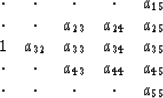
Another approach, that of predicting and removing undesired events might be to apply a filter shaped like that of Filter (12).
 |
(12) |
Another method of modifying the prediction quality is to introduce a gap between the output point of the filter and the free coefficients. For instance, Filter (11) might be modified to appear as
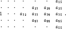 |
(13) |
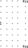
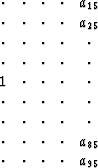
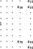
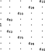
To remove events with a limited velocity range, filters such as
 ,
, ,
, , or
, or
 might be used.
The form of the filter would depend on the known velocity range of the
undesired events and how well the position of the coefficients fit
the events.
If the a15 and a95 coefficients fit the velocity of the
undesired events perfectly, only these two coefficients would be needed.
In general, since the grid on which the coefficients sit would not fit
a given velocity, the second filter with a15, a25, a85, and
a95 free would be needed.
If more than one event within the velocity range exists, or if events
dipping both directions with the same velocity exist within a window,
more columns with free coefficients will be needed. The last of the
previous filters may be needed in a practical case.
might be used.
The form of the filter would depend on the known velocity range of the
undesired events and how well the position of the coefficients fit
the events.
If the a15 and a95 coefficients fit the velocity of the
undesired events perfectly, only these two coefficients would be needed.
In general, since the grid on which the coefficients sit would not fit
a given velocity, the second filter with a15, a25, a85, and
a95 free would be needed.
If more than one event within the velocity range exists, or if events
dipping both directions with the same velocity exist within a window,
more columns with free coefficients will be needed. The last of the
previous filters may be needed in a practical case.
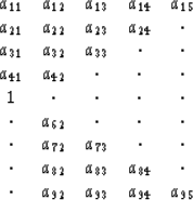
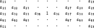
For the lateral prediction problem, the optimum filter shape is unclear. Ideally, a small filter with few coefficients is desired. As discussed above, a tall narrow filter such as Filter (8) would predict a single linear event. Adding more columns, such as in Filter (1) would allow more linear vents to be predicted. The number of time coefficients might be determined by the maximum dip expected. The safest filter, one with a large number of columns and rows, might be too expensive to calculate practically.
One might assume that a filter which is symmetric about the time and space axes would not require two passes of prediction. However, this is not the case. First, the calculation of Filter (14) shown below should be symmetric about the central coefficient, so calculating the other coefficients might be considered a waste of time.
 |
(14) |
As seen in the examples above in Filters (6) and (7), a filter with no free coefficients in the output column appears to have a forward prediction filter that is simply the reverse of the reverse prediction. This is not true with the filter with free coefficients in the output column.
While calculating small filters might be efficient, calculating larger filters involves n3 operations, where n is the number of coefficients to be calculated. Breaking large filters into smaller ones might reduce the computation significantly.