

Next: Conclusions
Up: DETECTION AND LOCATION OF
Previous: Application to microseismic data
Figure 15 shows the result of beam steering the data after
the first pass of surface noise suppression, where a single recorded
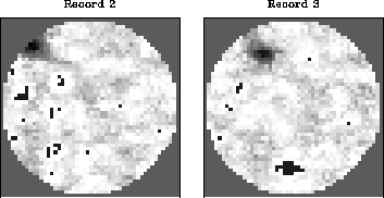
trace was used as the source waveform. Figure 16 shows
the result of beam steering after the second pass of surface
noise suppression, where the source waveform was computed by
stacking along the surface noise source's moveout trajectory.
Note the dark areas in the upper left of the plots in
Figure 16; these are not large semblance values
which have been clipped, but the small semblance values that
remain after surface noise suppression has done a very good
job.
It is interesting to note that beam steering suggests that
the second application of surface noise suppression was much
more effective, while the semblance results for the two
applications were comparable. Perhaps an improved method
of estimating the source signal would improve both results.
beam4
Figure 15 Beam steering after the first pass of surface noise suppression.
The algorithm has done a reasonably good job of suppressing the
surface noise source in the upper left. Other plane waves at
higher apparent velocities are relatively enhanced by the suppression
of the surface source.
 beam5
beam5
Figure 16 Beam steering after the second pass of surface noise suppression,
where the source waveform was created by stacking along the moveout
trajectory of the surface source. Now the algorithm has done a much
better job of suppressing the source, at least in Record 3. The
dark area near the upper left is not large amplitudes that have been
clipped; it is the small amplitudes that remain after the surface
source has been removed very well.


Next: Conclusions
Up: DETECTION AND LOCATION OF
Previous: Application to microseismic data
Stanford Exploration Project
1/13/1998

