next up previous [pdf]

Next: Polar coordinates Up: Canonical Examples Previous: Canonical Examples

Tilted Cartesian coordinates

Tilted Cartesian coordinates are a useful generalized migration coordinate system (see Figure 3a). () use this mesh in a plane-wave migration scheme where the coordinate system is oriented toward the plane-wave take-off angle to improve large-angle propagation accuracy. A tilted Cartesian mesh is defined by
$\displaystyle \left[ \begin{array}{c}
x_1\\
x_3
\end{array} \right] =
\left[ \...
...\end{array}\right]
\left[ \begin{array}{c}
\xi_1 \\
\xi_3
\end{array} \right],$     (14)

where $ \theta$ 
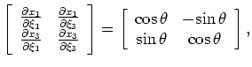
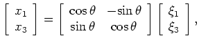
is the tilt angle. The partial derivative transform matrix is
$\displaystyle \left[ \begin{array}{cc}
\frac{\partial x_1}{\partial \xi_1}& \fr...
...in}   \theta \\
{\rm sin}   \theta & {\rm cos}   \theta
\end{array}\right],$     (15)

which leads to the following ADCIG equation:

$\displaystyle - \left. \frac{\partial \xi_3}{\partial h_{\xi_1}}\right\vert _{\...
...lpha + {\rm sin}  \theta  {\rm sin}   \alpha \right) } = {\rm tan}  \gamma.$ (16)

Thus, calculating ADCIGs in tilted Cartesian coordinates directly recovers the correct reflection opening angle. Note that setting $ \theta=0^\circ$ 
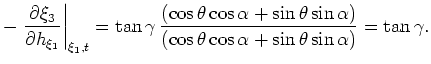
recovers the Cartesian expression in equation 8.
next up previous [pdf]

Next: Polar coordinates Up: Canonical Examples Previous: Canonical Examples

2009-04-13