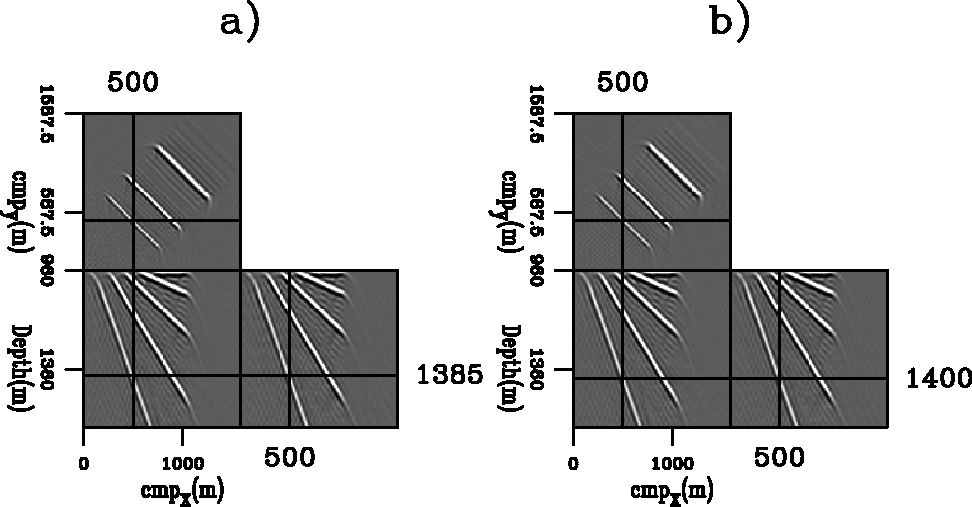
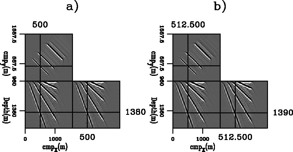
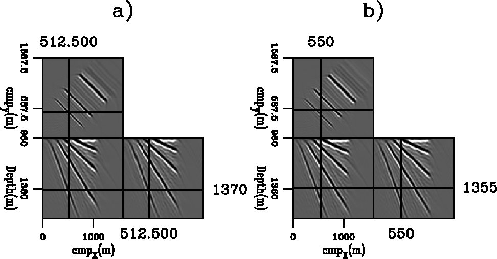
To verify the accuracy of our kinematic analysis of 3-D ADCIGs in presence of migration velocity errors, we compare the predictions of our results [equation (19) and equation (20)] with the actual reflector shifts in the angle-domain image cube obtained from a simple synthetic data set. The data set is the same as the one used in the previous section (5 dipping planes immersed in a vertically layered velocity function). We have migrated the data with a velocity function 3% slower than the correct one; that is, the slowness function is scaled by 1.03 at every depth level.
As we have discussed in the previous sections,
the azimuth of the reflections ![]() increases as the aperture angle
increases as the aperture angle ![]() increases.
Therefore, equation (19) and the RMO function
define curved lines that live in a 5-D space.
To verify their accuracy in predicting actual reflector
movements we display the image cube for the
following three pairs of
increases.
Therefore, equation (19) and the RMO function
define curved lines that live in a 5-D space.
To verify their accuracy in predicting actual reflector
movements we display the image cube for the
following three pairs of ![]() and
and ![]() :
:![]() in Figure 14,
in Figure 14,
![]() ,
,![]() in Figure 15,
and
in Figure 15,
and
![]() ,
,![]() in Figure 16.
These are the reflections' angles
for
the steepest (60 degrees dip) reflector
when the velocity is correct,
consistently with our
assumption of unperturbed rays.
All these figures display orthogonal sections cut
through the image cube at fixed
in Figure 16.
These are the reflections' angles
for
the steepest (60 degrees dip) reflector
when the velocity is correct,
consistently with our
assumption of unperturbed rays.
All these figures display orthogonal sections cut
through the image cube at fixed
![]() and
and ![]() and function
of the physical coordinates z, x, and y.
In panels a)
the cross-hairs are centered
at the coordinates predicted
using equation (19);
whereas
in panels b)
the cross-hairs are centered
at the coordinates predicted
by the 3-D RMO function expressed in
equation (20).
The numerical values of these coordinates are shown by
the numbers at the edges of the black lines
that define the cross-hairs.
and function
of the physical coordinates z, x, and y.
In panels a)
the cross-hairs are centered
at the coordinates predicted
using equation (19);
whereas
in panels b)
the cross-hairs are centered
at the coordinates predicted
by the 3-D RMO function expressed in
equation (20).
The numerical values of these coordinates are shown by
the numbers at the edges of the black lines
that define the cross-hairs.
The predictions corresponding
to equation (19) were computed
starting from a numerical raytracing
of the reflected events using the correct velocity.
The traveltime perturbation ![]() was then computed
by integrating the slowness perturbations along the
unperturbed rays.
Given
was then computed
by integrating the slowness perturbations along the
unperturbed rays.
Given ![]() ,
,
![]() was computed using
equation (19).
If the background velocity were constant (straight rays)
the procedure outlined above would result
in image-point shifts exactly equal to the
image-point shifts computed using equation (20).
In our example the background velocity
increases with depth and therefore the two predictions
differ for large aperture angles.
was computed using
equation (19).
If the background velocity were constant (straight rays)
the procedure outlined above would result
in image-point shifts exactly equal to the
image-point shifts computed using equation (20).
In our example the background velocity
increases with depth and therefore the two predictions
differ for large aperture angles.
The cross-hairs in the panels on the left accurately track the reflector movements in the corresponding image cubes. These panels demonstrate that equation (19) accurately predicts the actual movements of the reflector across the whole range of aperture angles, even if the reflector analyzed is steeply dipping at 60 degrees.
As expected, the predictions computed by applying
equation (20) (panels b)
are not as accurate as the predictions
computed using
equation (19) (panels b).
Consistently to the intended use of RMO functions,
the shift at normal incidence (![]() )was picked from the image, whereas the
shifts at
)was picked from the image, whereas the
shifts at ![]() and at
and at ![]() were computed using equation (20).
The predicted shifts track fairly
well the reflector movements in the image
up to an aperture angle of 20 degrees
(Figure 15b),
but the straight-rays approximation underlying
our derivation of the 3-D RMO function breaks
down when either the source or the receiver
rays are close to overturning.
As it is easy to verify by simple
trigonometry,
when
were computed using equation (20).
The predicted shifts track fairly
well the reflector movements in the image
up to an aperture angle of 20 degrees
(Figure 15b),
but the straight-rays approximation underlying
our derivation of the 3-D RMO function breaks
down when either the source or the receiver
rays are close to overturning.
As it is easy to verify by simple
trigonometry,
when ![]() and
and ![]() (Figure 16b)
the take-off angle
at the reflection point
is about 81 degrees for one of the two rays.
A straight ray propagating
at such an oblique angle is a poor approximation
of the true ray
that starts with the same take-off angle at the reflection point.
The true ray quickly becomes more
vertical as it travels toward the surface,
and consequently it is much shorter than the straight ray.
This break down of the assumptions at the basis of the
derivation of the 3-D RMO function,
causes the substantial overprediction of the reflector movements
observed in Figure 16b.
(Figure 16b)
the take-off angle
at the reflection point
is about 81 degrees for one of the two rays.
A straight ray propagating
at such an oblique angle is a poor approximation
of the true ray
that starts with the same take-off angle at the reflection point.
The true ray quickly becomes more
vertical as it travels toward the surface,
and consequently it is much shorter than the straight ray.
This break down of the assumptions at the basis of the
derivation of the 3-D RMO function,
causes the substantial overprediction of the reflector movements
observed in Figure 16b.
 |
 |
 |
We present a new methodology for computing 3-D Angle Domain Common Image Gathers (ADCIGs) from the results of wavefield-continuation migration. The proposed methodology is general and can be applied to the results obtained with any wavefield-continuation migration method, including: downward-continuation shot-profile migration, reverse-time shot-profile migration, source-receiver migration, and plane wave migration. Furthermore, our method can be used to compute ADCIGs before imaging and after imaging. These two kinds of ADCIG are related, though we show that they have a different sensitivity to velocity errors.
We successfully applied the proposed methods to the computation
of 3-D ADCIGs from a simple
synthetic data set.
3-D ADCIGs represent reflections as a function of
the reflection azimuth ![]() ,in addition to the aperture angle
,in addition to the aperture angle ![]() .Whereas reflection azimuth is obviously related to the data azimuth,
our synthetic-data example demonstrates that they may differ
when velocity variations in the overburden
distort the wavefield.
In the general case,
both
.Whereas reflection azimuth is obviously related to the data azimuth,
our synthetic-data example demonstrates that they may differ
when velocity variations in the overburden
distort the wavefield.
In the general case,
both ![]() and
and ![]() are needed to
characterize the events and
to use ADCIGs for either amplitude analysis or
Migration Velocity Analysis (MVA)
are needed to
characterize the events and
to use ADCIGs for either amplitude analysis or
Migration Velocity Analysis (MVA)
To enable the application of 3-D ADCIGs to MVA, we generalize the kinematic analysis of 2-D ADCIGs in presence of migration-velocity errors Biondi and Symes (2003). Our analysis yields a quantitative relationship between depth errors measurable in 3-D ADCIGs and traveltime perturbations caused by velocity errors. This relationship can be directly used in a ray-based MVA procedure. In this paper, we use it for deriving an approximate 3-D Residual Moveout (RMO) function that predicts reflectors' movement when migration velocity is inaccurate. Our derivation of the 3-D RMO function assumes straight rays.
We confirm the accuracy of our kinematic analysis by comparing the image-point shifts predicted by its results with the actual reflector's shifts in the angle-domain image cube obtained from a 3-D synthetic data set with steeply dipping reflectors and a vertically varying propagation velocity. The proposed 3-D RMO function is accurate for a wide range of dips and aperture angles. However, as expected, when rays are close to overturn the straight-rays approximation is inadequate, and the 3-D RMO function overpredicts the actual reflector's movements.
We would like to thank Sam Gray for useful discussions on ADCIGs and for pointing out to us that a plane-wave interpretation of 3-D ADCIGs would overcome the difficulties encountered by a ray-theoretical one.