| |
(1) |
A practical way to compute the reflectivity strength is discussed in Claerbout's paper Claerbout (1971). The reflectivity strength is computed as:
| |
(2) |
A more general imaging condition can be stated, computing the reflectivity strength as:
| |
(3) |
Figures ![[*]](http://sepwww.stanford.edu/latex2html/cross_ref_motif.gif) to
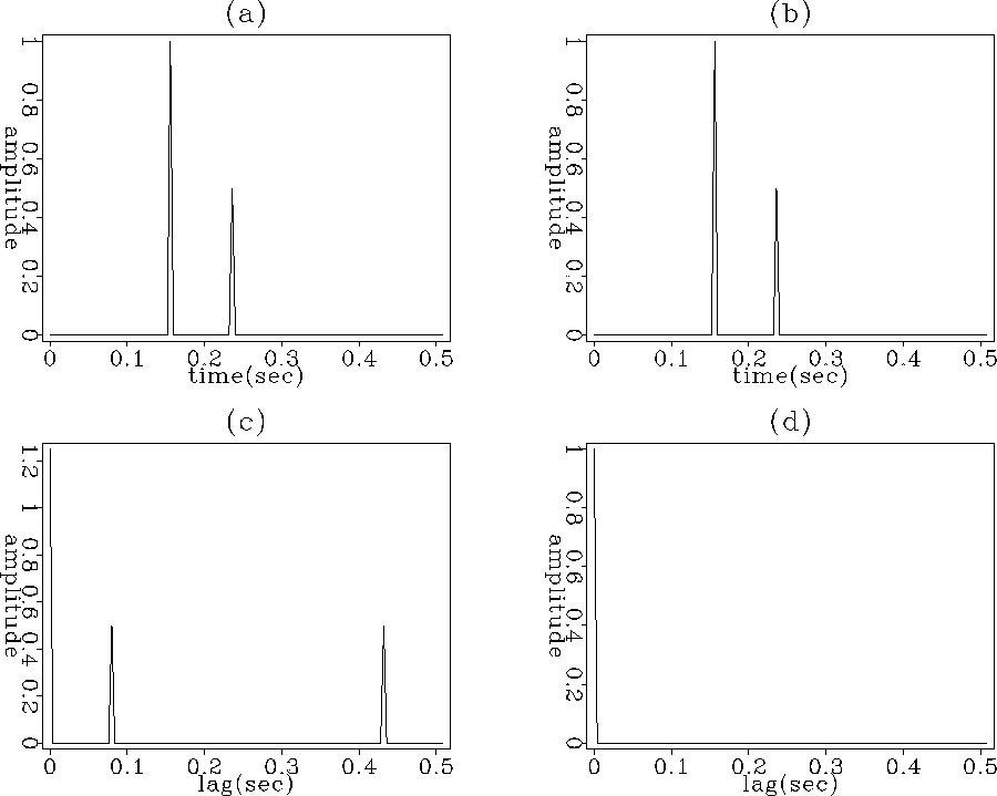
to ![[*]](http://sepwww.stanford.edu/latex2html/cross_ref_motif.gif) show the comparison of wavefield deconvolution with wavefield cross-correlation imaging condition. The first row, in Figure
show the comparison of wavefield deconvolution with wavefield cross-correlation imaging condition. The first row, in Figure ![[*]](http://sepwww.stanford.edu/latex2html/cross_ref_motif.gif) , simulates the two wavefields coinciding at the reflector depth. The result of the cross-correlation and the result of the deconvolution is shown in the second row. For each case, the zero lag of the wavefield cross-correlation or the zero lag of the wavefield deconvolution is assigned as the reflectivity strength at this depth.
, simulates the two wavefields coinciding at the reflector depth. The result of the cross-correlation and the result of the deconvolution is shown in the second row. For each case, the zero lag of the wavefield cross-correlation or the zero lag of the wavefield deconvolution is assigned as the reflectivity strength at this depth.
|
spike
Figure 1 Wavefields coinciding at the reflector depth. (a) Source wavefield. (b) Receiver wavefield. (c) Wavefields cross-correlation. (d) Wavefields deconvolution. |  |
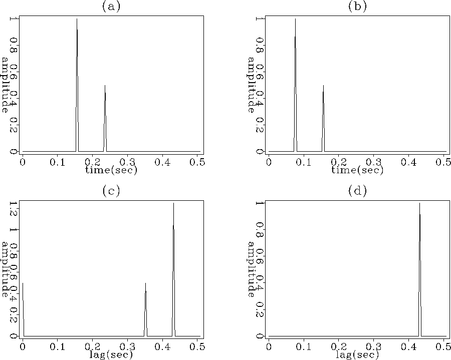
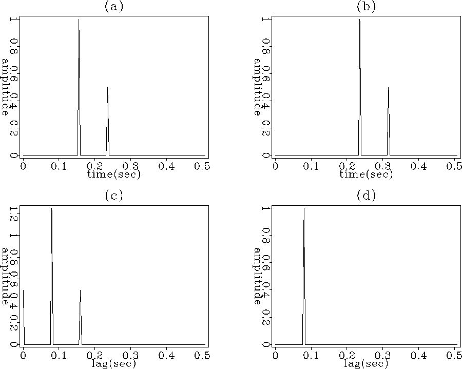
The first row in Figure ![[*]](http://sepwww.stanford.edu/latex2html/cross_ref_motif.gif) /
/ ![[*]](http://sepwww.stanford.edu/latex2html/cross_ref_motif.gif) simulates the two wavefields at a deeper / shallower depth than the reflector depth. The second row shows the result of the cross-correlation and the result of the deconvolution. The zero lag value of the wavefield cross-correlation has a value different than zero, thus creates an image artifact at a deeper / shallower depth. In the case of deconvolution imaging condition, the zero lag value is zero, thus no image artifacts are created.
simulates the two wavefields at a deeper / shallower depth than the reflector depth. The second row shows the result of the cross-correlation and the result of the deconvolution. The zero lag value of the wavefield cross-correlation has a value different than zero, thus creates an image artifact at a deeper / shallower depth. In the case of deconvolution imaging condition, the zero lag value is zero, thus no image artifacts are created.
|
spike1
Figure 2 Wavefields at a depth deeper the reflector depth. (a) Source wavefield. (b) Receiver wavefield. (c) Wavefields cross-correlation. (d) Wavefields deconvolution. |  |
|
spike2
Figure 3 Wavefields at a depth shallower the reflector depth. (a) Source wavefield. (b) Receiver wavefield. (c) Wavefields cross-correlation. (d) Wavefields deconvolution. |  |
The imaging condition stated in equation (3) makes the strong assumption that the receiver wavefield ![]() can be computed by convolving the source wavefield
can be computed by convolving the source wavefield ![]() by the reflectivity strength
by the reflectivity strength ![]() . As we will discuss later, this is true at the reflector depth, but might not be true at a different depth.
. As we will discuss later, this is true at the reflector depth, but might not be true at a different depth.