![[*]](http://sepwww.stanford.edu/latex2html/cross_ref_motif.gif) I show how many of these problems
are solved when the problem is addressed in a 3-D context.
I show how many of these problems
are solved when the problem is addressed in a 3-D context.
In each example presented in this chapter the final migrated
image (Figures 15 and 20)
still seemed to show room for improvement.
The top of the salt was not well defined, especially around x=7 km.
We were not able to see the left salt edge and the reflectors
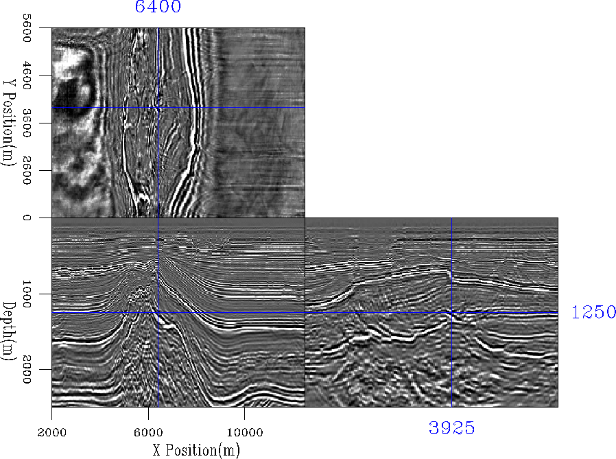
did not extend as far as anticipated. Figure 21 shows
some of the reason. The front panel shows the same cross-line
location used in this chapter. The right panel shows a cross-line
view of the structure along the upper salt top. The complicated
cross-line structure means that a 2-D method has little chance
of either finding the correct velocity or properly imaging.
Reflectors below the salt edge are also effected by this 3-D structure.
In chapter ![[*]](http://sepwww.stanford.edu/latex2html/cross_ref_motif.gif) I show how many of these problems
are solved when the problem is addressed in a 3-D context.
I show how many of these problems
are solved when the problem is addressed in a 3-D context.
 |