

Next: Implementation details
Up: Sava & Fomel: Huygens
Previous: Continuous theory
A natural first-order discretization scheme for equation (5) leads
to the difference equation
|  |
(7) |
where the index i corresponds to the ray parameter  , j
corresponds to the traveltime
  ,
,  ,
, is the increment in time, and vji is the velocity
at the
  grid point. It is easy to notice that equation
(7) simply describes a sphere (or a circle in two
dimensions) with the center at
  and the radius
rji. This sphere is, of course, the wavefront of a secondary Huygens
source.
This observation suggests that we apply the Huygens' principle
directly to find an appropriate discretization for equation
(6). Let us consider a family of Huygens spheres, centered
at the points along the current wavefront. Mathematically, this family
is described by an equation analogous to (7), as follows:
|  |
(8) |
Here the ray parameter  serves as the parameter that
distinguishes a particular Huygens source. According to the Huygens'
principle, the next wavefront corresponds to the envelope of the
wavefront family. To find the envelop condition, we can simply
differentiate both sides of equation (8) with respect to
the family parameter
  . The result takes the form
|  |
(9) |
which is clearly a semidiscrete analog of equation (6).
To complete the discretization, we can represent the
 -derivatives in (9) by a centered
finite-difference approximation. This representation yields the scheme
|  |
(10) |
which supplements the previously found scheme (7) for a
unique determination of the point  on the
i-th ray and the (j+1)-th wavefront. Formulas (7)
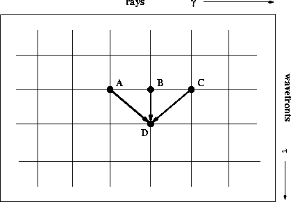
and (10) define an update scheme, depicted in Figure
1. To fill the
  plane, the scheme
needs to be initialized with one complete wavefront (around the wave
source) and two boundary rays.
The solution of system (7-10) has the
explicit form
|  |
(11) |
| (12) |
where
|  |
(13) |
and
|  |
(14) |
scheme
Figure 1 An updating scheme for HWT. Three
points on the current wavefront (A, B, and C) are used to advance
in the  direction. direction.
|
|  |

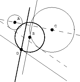
Figure 2 shows a geometric interpretation of formulas
(7) and (10). Formula (10) is
clearly a line equation. Thus, the new point D in Figure
2 is defined as one of the two intersections of this
line with the B sphere, defined by formula (7). It is
easy to show geometrically that the newly created ray segment BD is
orthogonal to the common tangent of spheres A and C. Within the
finite-difference approximation, the common tangent reflects local
wavefront behavior.
huygens
Figure 2 A geometrical updating scheme for
HWT in the physical domain. Three points on the current
wavefront (A, B, and C) are used to compute the position of the
D point. The bold lines represent equations (7) and
(10). The tangent to circle B at point D is parallel to
the common tangent of circles A and C.
|
|  |


Next: Implementation details
Up: Sava & Fomel: Huygens
Previous: Continuous theory
Stanford Exploration Project
9/12/2000


