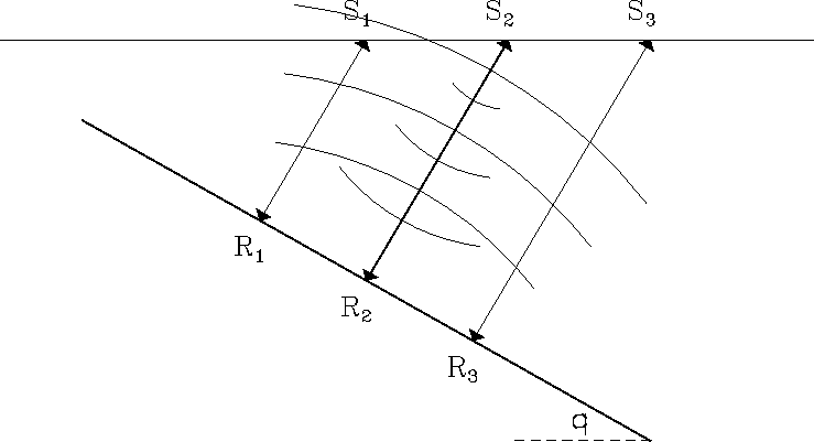
Consider the zero-offset seismic survey shown in Figure 1.
This survey uses one source-receiver pair,
and the receiver is always at the same location as the source.
At each position, denoted by
![]() in the figure,
the source emits waves and the receiver records the echoes
as a single seismic trace.
After each trace is recorded,
the source-receiver pair is moved a small distance
and the experiment is repeated.
in the figure,
the source emits waves and the receiver records the echoes
as a single seismic trace.
After each trace is recorded,
the source-receiver pair is moved a small distance
and the experiment is repeated.
|
reflexpt
Figure 1 Raypaths and wavefronts for a zero-offset seismic line shot above a dipping reflector. The earth's propagation velocity is constant. |  |
As shown in the figure, the source at S2 emits a spherically-spreading wave that bounces off the reflector and then returns to the receiver at S2. The raypaths drawn between Si and Ri are orthogonal to the reflector and hence are called normal rays.
These rays reveal how the zero-offset section misrepresents the truth. For example, the trace recorded at S2 is dominated by the reflectivity near reflection point R2, where the normal ray from S2 hits the reflector. If the zero-offset section corresponding to Figure 1 is displayed, the reflectivity at R2 will be falsely displayed as though it were directly beneath S2, which it certainly is not. This lateral mispositioning is the first part of the illusion. The second part is vertical: if converted to depth, the zero-offset section will show R2 to be deeper than it really is. The reason is that the slant path of the normal ray is longer than a vertical shaft drilled from the surface down to R2.