Next: Example 3 - GRWE
Up: Shragge: GRWE
Previous: Example 1 - 2-D
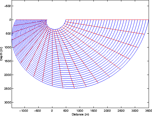
A second instructive example is a stretched polar coordinate system
(see figure ![[*]](http://sepwww.stanford.edu/data/media/public/sep/latex2html/cross_ref_motif.gif) ). A polar ellipsoidal coordinate
system is specified by,
). A polar ellipsoidal coordinate
system is specified by,
| ![\begin{displaymath}
\left[\begin{array}
{c}
x_1\ x_3
\end{array}\right]
=...
...3 \ a(\xi_3)\,\xi_1\, \rm{sin}\,\xi_3 \ \end{array}\right].\end{displaymath}](img61.gif) |
(29) |
Parameter  is a smooth function controlling coordinate
system ellipticity and has curvature parameters
is a smooth function controlling coordinate
system ellipticity and has curvature parameters  and
and  .The metric tensor gij is,
| ![\begin{displaymath}
\left[g_{ij}\right]
=
\left[\begin{array}
{cc}
a^2 & \xi_1\, a\, b \ \xi_1 \, a \, b & \xi_1^2(b^2+a^2) \end{array}\right],\end{displaymath}](img65.gif) |
(30) |
with determinant  . The associated metric and
weighted associated metric tensors are given by,
. The associated metric and
weighted associated metric tensors are given by,
| ![\begin{displaymath}
\left[g^{ij}\right]
=
\left[\begin{array}
{cc}
\frac{b^2+a^...
...rac{b}{a} \ -\frac{b}{a} & \frac{1}{\xi_1}\end{array}\right].\end{displaymath}](img67.gif) |
(31) |
2Dex2
Figure 3 Polar ellipsoidal coordinate
system example.
|
|  |

Tensors gij and mij specify a wavenumber appropriate for
extrapolating wavefields on a 2-D non-orthogonal mesh (see
equation 41). However, because the coordinate system is
spatially variant, we must also compute the ni fields:
 and n3=0. Inserting these values
yields the following extrapolation wavenumber
and n3=0. Inserting these values
yields the following extrapolation wavenumber  ,
,
|  |
(32) |
The kinematic version of equation 32 is,
| ![\begin{displaymath}
k_\xi_3= \xi_1 \left[\frac{b}{a} k_\xi_1\pm \sqrt{ a^2 s^2 \omega^2 -
k_\xi_1^2 }\right], \end{displaymath}](img70.gif) |
(33) |
while the orthogonal polar case (i.e. a=1) recovers the following,
| 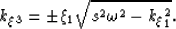 |
(34) |
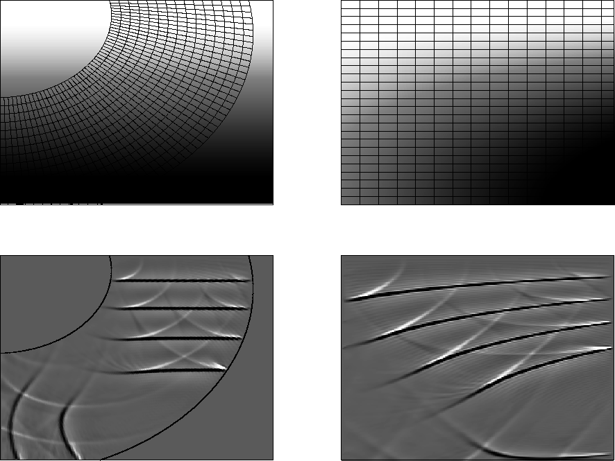
Figure shows an ellipsoidal polar coordinate
system defined by 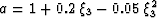 . The upper
left panel shows a
. The upper
left panel shows a 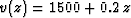 velocity function overlain by
a coordinate system mesh. The upper right panel presents velocity
model as mapped into the GRWE domain. The data used in this test
consisted of 4 flat plane-waves. Given this experimental setup,
propagating flat plane-waves should not bend in the Cartesian domain
because of the v=v(z) velocity model, even though there is velocity
variation across each extrapolation step in the GRWE domain. Hence,
the impulses have curvature in the GRWE domain (lower right panel).
The lower left panel shows the GRWE domain imaging results mapped back
to a Cartesian domain. Consistent with theory, the flat plane-waves
are imaged as flat reflectors. Note that the edge effects are again
caused by coordinate system and plane-wave truncation.
velocity function overlain by
a coordinate system mesh. The upper right panel presents velocity
model as mapped into the GRWE domain. The data used in this test
consisted of 4 flat plane-waves. Given this experimental setup,
propagating flat plane-waves should not bend in the Cartesian domain
because of the v=v(z) velocity model, even though there is velocity
variation across each extrapolation step in the GRWE domain. Hence,
the impulses have curvature in the GRWE domain (lower right panel).
The lower left panel shows the GRWE domain imaging results mapped back
to a Cartesian domain. Consistent with theory, the flat plane-waves
are imaged as flat reflectors. Note that the edge effects are again
caused by coordinate system and plane-wave truncation.
Polar
Figure 4 Ellipsoidal polar coordinate
system test example. Upper left: velocity
function overlain by a polar ellipsoidal coordinate system defined
by parameter . Upper right: velocity
model in the GRWE domain. Bottom right: Imaged reflectors in GRWE
domain. Bottom left: the GRWE domain image mapped to a Cartesian
mesh.


Next: Example 3 - GRWE
Up: Shragge: GRWE
Previous: Example 1 - 2-D
Stanford Exploration Project
4/5/2006