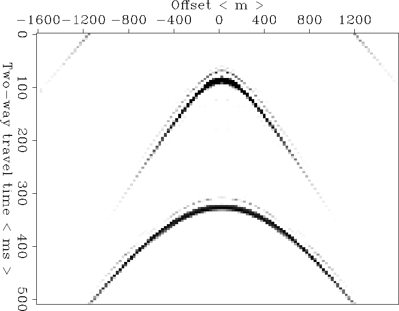
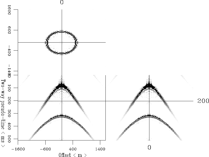
To illustrate the focusing analysis methodology, we chose a 2-D and 3-D CMP phase-shift migration operator, the simplest operator deduced from the double square root operator. Working with two filtered spikes with a central frequency 30Hz and a constant velocity of 3000 m/s, the operator modeled a CMP gather recorded at the surface with a 25 m between traces and 4ms for temporal sampling, as shown in the Figure 4 for the 2-D modeling and Figure 8 for the 3-D modeling.
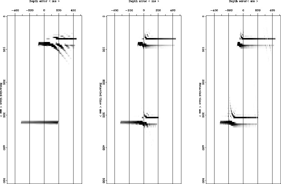
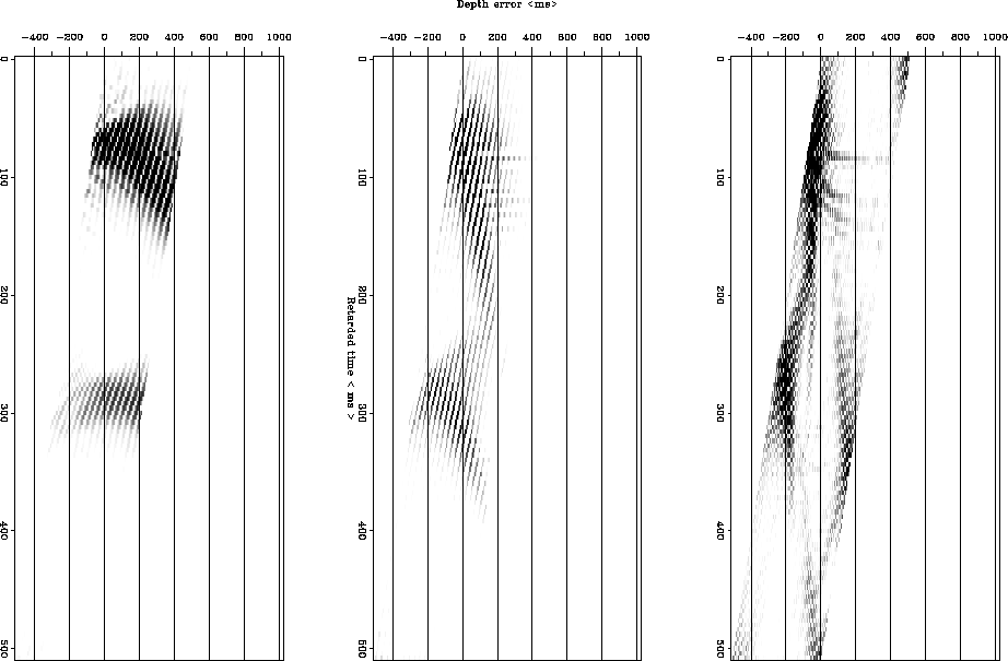
This CMP gather is downward continued with the 2-D and 3-D operator (adjoint operator)with a constant velocity to build the depth error gather for this CMP gather (see Figures 6 and 7 for the 2-D case and Figure 9 for the 3-D case). For every downward continuation step of migration (adjoint) operator, the zero-offset trace is stored. In the 2-D diffractor migration the depth error panels are plotted in Figures (6) and 7. Because we are using a phase-shift operator there is aliasing noise in the depth error gathers.
Figure 6 shows the depth error gather obtained when
the CMP is downward continued with constant velocity Vm=3000m/s
equal to the real propagation velocity, Vr. This result shows when
Vm=Vr, the energy at the zero-offset trace is maximum when
depth error, ![]() , is equal to zero for both point diffractors. In contrast,
the depth error is different of zero in the depth error gathers
obtained with a downward continuation velocity, Vm, is not equal to the
real propagation velocity.
Moreover, the 2-D depth error gather shows a
phase difference of 90 degrees indicating the maximum focusing
energy, as is predicted by the 2-D migration theory
Doherty and Claerbout (1974).
, is equal to zero for both point diffractors. In contrast,
the depth error is different of zero in the depth error gathers
obtained with a downward continuation velocity, Vm, is not equal to the
real propagation velocity.
Moreover, the 2-D depth error gather shows a
phase difference of 90 degrees indicating the maximum focusing
energy, as is predicted by the 2-D migration theory
Doherty and Claerbout (1974).
Another interesting feature of the error gather is the linear trend in the condition of maximun focusing, because of the far-offsets. In contrast, the depth error gather build with a 3-D downward continuation operator does not present that change in phase (see Figure 9) as predicts the theory.
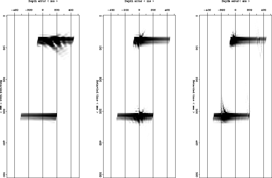
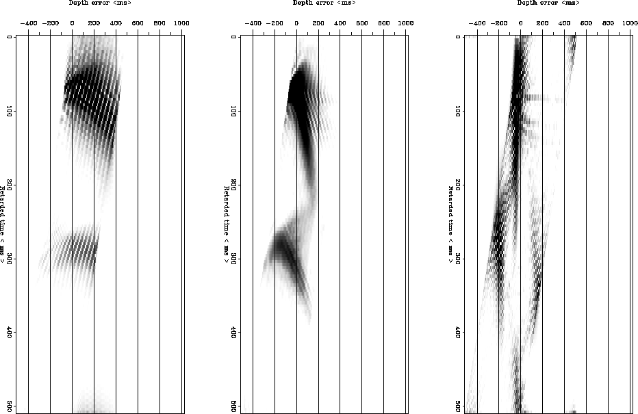
The depth error gather is usually plotted by taking the envelope of every trace in the gather (see Figure 7). This is because that depth focusing analysis method is based on a 2-D operator and to eliminate the phase difference mentioned before. We show depth error panels with the trace and with the envelope to emphasize the difference between the the depth error gather built with a 2-D downward continuation operator and the gather built with a 3-D operator.
Comparing the error panels built with a 2-D and 3-D downward continuation phase-shift operator in the CMP domain for constant velocity, shows the independence on the dimensionality of the data (see Figures 6, 7, 9 and 10). This is an important result in the implementation the depth focusing methodology in 3-D for velocity estimations. Moreover, it is a 2-D gather making it easy to interpret and to estimate the real propagation velocity by picking the depth error defined by the focal point on the depth error gather and using the equations 9 and 4 the real propagation velocity Vr and the real depth Zr are estimated from a wrong migration velocity Vm and a wrong focusing depth Zf as equation (1).
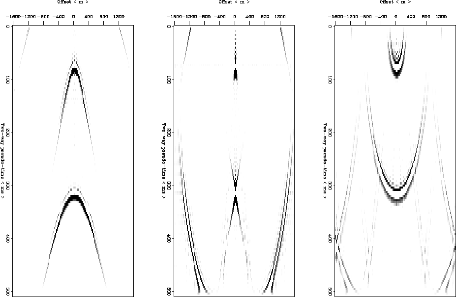
Analyzing the 2-D spike migrations with different velocities of the Figure 5, we can interpret them as three differents steps in the downward continued process of the CMP with just one velocity higher than 4000m/s. Hence a depth error gather can be interpreted as a set of zero-offsets traces with different velocities, increasing from negative error to positive errors 1994.
Figures 9 and 10 presents the error gather built from a 3-D phase-shift downward continuation operator in CMP domain for two points diffractor, as in the 2-D case.We tested three differents constant migration velocities. The depth error panel obtained with Vm=2000m/s, we observe that the energy is focusing for a positive depth error. It shows that the migration velocity was low and the focusing depth and the real depth, are greater than the migration depth. For a migration velocity equal to the real propagation velocity, as spected there is not error in depth. When the migration velocity is 4000m/s the focusing point has a negative depth error negative because the velocity is higher than the real velocity. In addition, we can observe a banded behavior on the 3-D depth error panels and it is smooth when we displayed the same panel by the envelope (see Figure 10).
 |
 |
 |
 |
 |
 |
 |