|
|
|
|
Least-squares imaging and deconvolution using the hybrid norm conjugate-direction solver |
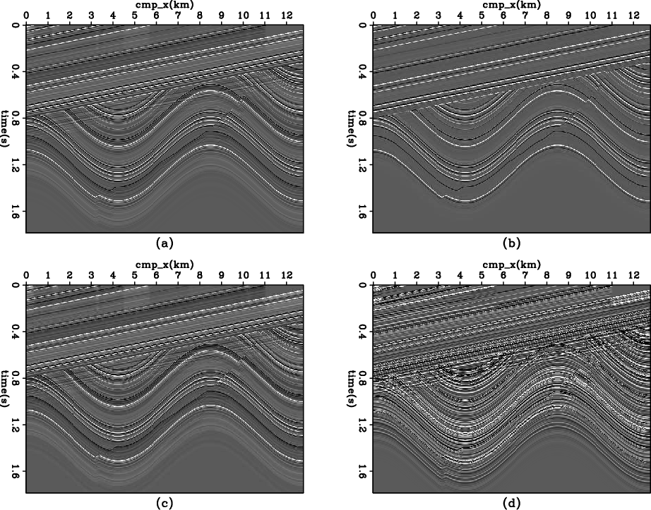
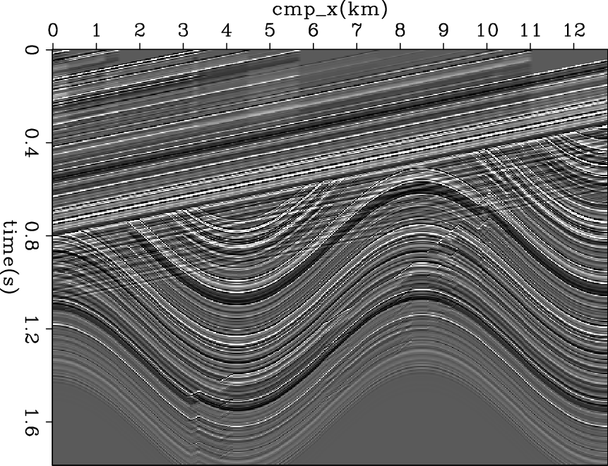
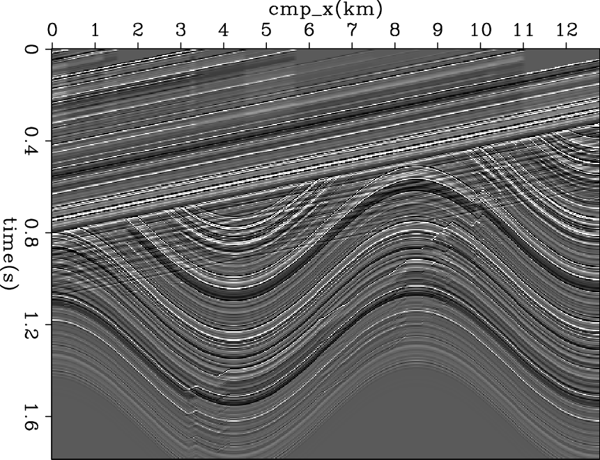
Figure 5 compares the result of L2 inversion
and L1
inversion (using the hybrid norm). As expected, the conventional L2 result gives
a fuzzy model poorly correlated to the original one. In contrast, the hybrid result
recovers the original model quite well. For verification,
the data residuals are plotted at the bottom of Figure 5;
the hybrid result has a fitting error of 0.6%, indicating that the data fitting goal is well honored.
|
|---|
|
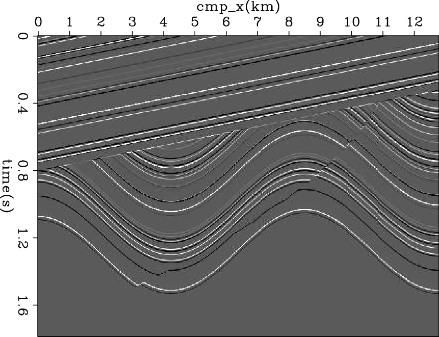
refl-syn-decon
Figure 3. Reflectivity model. |
|
|
|
|---|
|
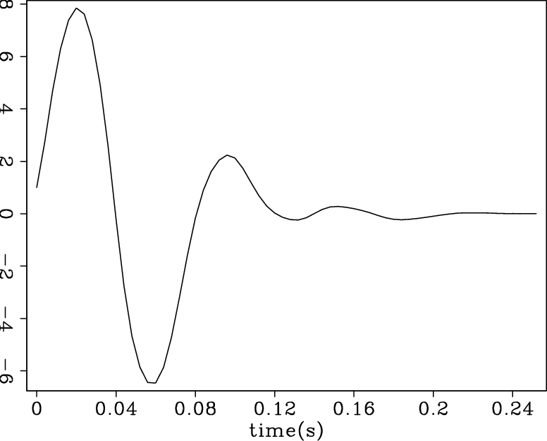
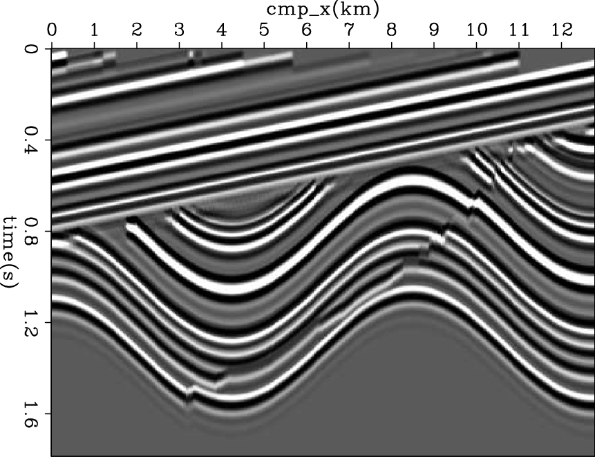
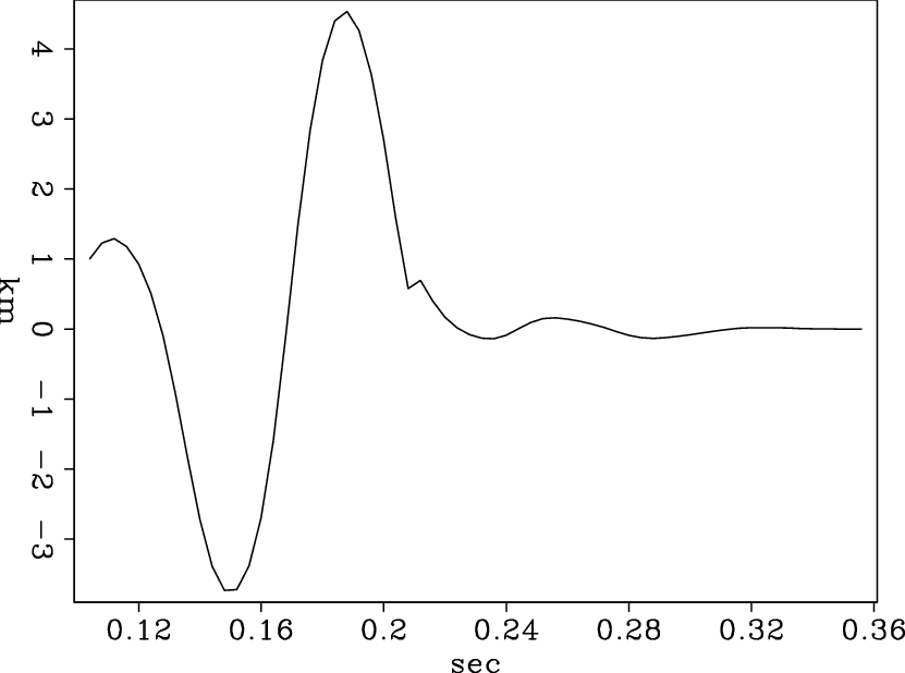
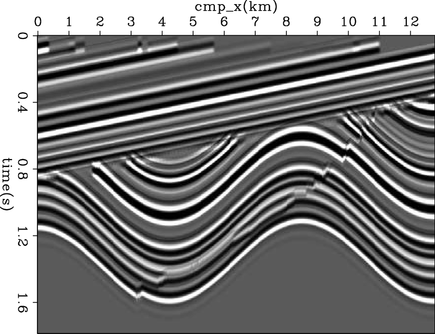
wavelet-syn-decon,data-syn-decon
Figure 4. Synthetic Data for deconvolution. (a): The minimum phase wavelet; (b): generated input data. |
|
|
|
|---|
|
syn-decon
Figure 5. Comparison of deconvolution result for synthetic data. Top panels show the reflectivity model obtained by L2 inversion (a) and hybrid inversion (b); bottom panels (c)(d) show the respective data residual. |
|
|
One limitation of the formulation (4) is the assumption of a minimum phase wavelet. A non-minimum phase signal does not have a causal inverse in theory, thus breaking our formulation (4) since the filter a that is supposed to be the inverse of source wavelet does not exist.
To see how much the non-minimum phase wavelet will affect the inversion
result, we performed another experiment in which the
wavelet is chosen to be a non-minimum phase one.
Figure 6 shows the new
wavelet and the synthetic data generated using this wavelet.
Figure 7 shows the result of L2 inversion
and L1 inversion (using the hybrid norm) of this data, using the same
parameters as in the previous synthetic example. In contrast to the
significant improvement obtained before, the hybrid result
cannot yield a sparse model because it is impossible to find a
filter a that undoes the source wavelet.
|
|---|
|
wavelet-syn-mix-decon,data-syn-mix-decon
Figure 6. (a): the mixed-phase wavelet; (b): generated data. |
|
|
|
|---|
|
result-syn-mix-decon-l2,result-syn-mix-decon-hb
Figure 7. (a): L2 inversion result for the synthetic data generated with mixed-phase wavelet;(b): hybrid inversion result. |
|
|
|
|
|
|
Least-squares imaging and deconvolution using the hybrid norm conjugate-direction solver |