|
mig
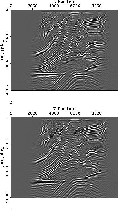
Figure 3 Comparison of the zero-subsurface offset image from implementing the shot profile imaging condition on the processor (top) and the FPGA (bottom). |  |
![[*]](http://sepwww.stanford.edu/latex2html/cross_ref_motif.gif) show the zero-subsurface offset image obtained
from implementing the imaging step of shot profile migration on both
the processor and the FPGA. The images are indistinguisable.
show the zero-subsurface offset image obtained
from implementing the imaging step of shot profile migration on both
the processor and the FPGA. The images are indistinguisable.
|
mig
Figure 3 Comparison of the zero-subsurface offset image from implementing the shot profile imaging condition on the processor (top) and the FPGA (bottom). |  |
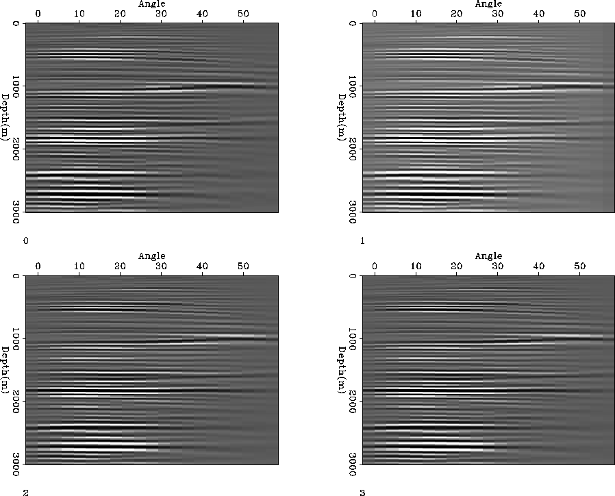
The left panel of Figure ![[*]](http://sepwww.stanford.edu/latex2html/cross_ref_motif.gif) shows an angle gather constructed
from the CPU implementation of the imagining condition. The
remaining panels show the same angle gather obtained from
the FPGA implemented imaging condition with decreasing floating
point precision. Note that visually the kinematics are identical.
shows an angle gather constructed
from the CPU implementation of the imagining condition. The
remaining panels show the same angle gather obtained from
the FPGA implemented imaging condition with decreasing floating
point precision. Note that visually the kinematics are identical.
 |
To test the speed-up offered by the FPGA implementation we ran
a larger 3-D problem. Specifically the cost of constructing 41 subsurface
offset gathers from 500 inline CMPS, 400 crossline cmnps, 200 frequencies,
and 41 subsurface offsets.
We compare our FPGA implementation to a 2.8Ghz AMD Opteron-based PC with 12GB of RAM. The software implementation was written in C and compiled using both gcc and the Intel C Compiler with full optimization, the average of three runs was selected. The FPGA accelerator was implemented on a Maxeler MAX-1 FPGA platform equipped with a Xilinx Virtex-4 FX100 FPGA. The accelerator circuit consumes 58% of the logic resources of the device and runs at 125Mhz.
Table 1 shows the runtimes for the gather operation at a single depth and shot, carried out both in software and on the FPGA. The FPGA computes the gather 19-21 times faster than the software using 32-bit data, or 35-42 times faster than the software using 16-bit data. This degree of acceleration transforms the application space, instead of the subsurface offset gather being dominant the time spent computing it is now insignificant as a portion of the overall runtime.
| ny | Tsw | Tfpga32 | Speed-up | Tfpga16 | Speed-up |
| 1 | 0.041 | 0.002 | 21x | 0.001 | 41x |
| 50 | 1.48 | 0.073 | 20x | 0.042 | 35x |
| 100 | 2.76 | 0.149 | 19x | 0.075 | 37x |
| 200 | 6.40 | 0.311 | 21x | 0.150 | 42x |