![[*]](http://sepwww.stanford.edu/latex2html/cross_ref_motif.gif) and 2.
The top row simulates six bits, the center 8 bits, and the bottom
9 bits.
In this case it takes 9 bits to get the error down to
less than 1%.
and 2.
The top row simulates six bits, the center 8 bits, and the bottom
9 bits.
In this case it takes 9 bits to get the error down to
less than 1%.
Downward continuing a wavefield in a v(x,z) medium has three basic computational parts that are constantly repeated: multiplication by a correction factor, Fast Fourier Transform (FFT), and multiplication by a complex exponential. At least two, and potentially all three, would be good candidates for an FPGA. Other poritions of the downward continuation process such as managing wavefields to handle multiple reference velocities would be inappropriate. As a result what we need to limit are internal data representation so we can reduce the number of bits that need to be sent to and from the external hardware device. This makes the error analysis of the last section much more complicated.
The fact that we only need to produce an image that is accurate
to about 1000 quantization intervals gives us some hope. The
FFT operation is a series of intergals, so the same error analysis
can be performed. We are not summing over
a large number of points at every step in the downward continuation
process so we will need more precision than before.
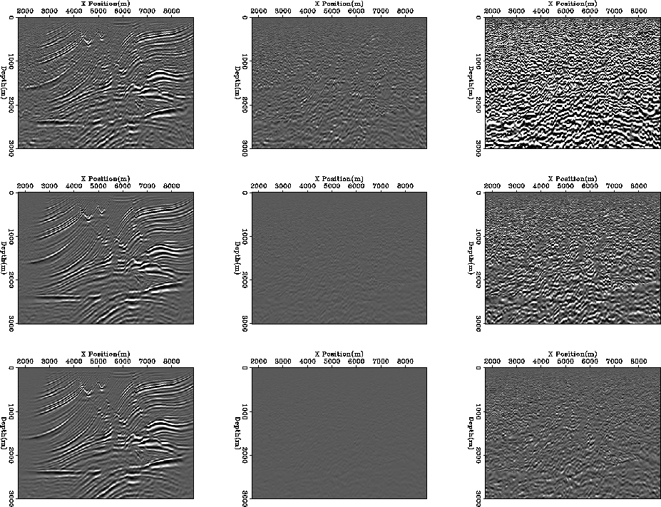
Figure 3
is the same design as Figures ![[*]](http://sepwww.stanford.edu/latex2html/cross_ref_motif.gif) and 2.
The top row simulates six bits, the center 8 bits, and the bottom
9 bits.
In this case it takes 9 bits to get the error down to
less than 1%.
and 2.
The top row simulates six bits, the center 8 bits, and the bottom
9 bits.
In this case it takes 9 bits to get the error down to
less than 1%.
 |
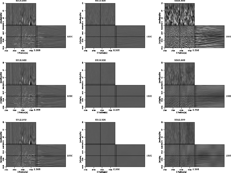
To produce acceptable angle gathers requires significantly more bits. Figure 4 is in the same form as the previous figures. The top row simulates nine bits, the center 11 bits, and the bottom row 12 bits. To get the error below two percent requires a significant bit representation, but for almost all applications the nine bit representation is more than acceptable.
 |