

Next: Cost-efficient prestack exploding-reflector modeling
Up: Prestack exploding reflector modeling
Previous: Modeling of an isolated
The experiment modeled following the procedure described above
can be imaged by using conventional migration of aerial shot data.
For example, the reverse time migration of the data can be expressed as:
|  |
(9) |
where the source and receiver data provide the surface
boundary conditions to generate the
source wavefield  and the receiver wavefield
  .
.
To theoretically analyze the migration results we can express these wavefields
as function of the data convolved, both in time and space,
with the convolutional operator
G1,
that represents the propagation from the surface into the subsurface.
For the sake of simplicity, I limit this analysis to
the flat-reflector case,
where the wavefields at depth can be written as:
|  |
(10) |
| (11) |
Similarly, the data themselves can be represented as the convolution
of the image (exploding reflectors) with the operator
G0
representing the propagation from the subsurface up to the surface;
that is, as:
|  |
(12) |
| (13) |
Substituting equation 12 into
equation 10,
and
equation 13 into
equation 11,
I obtain:
|  |
(14) |
| (15) |
In general,
the velocity models used for modeling
and migration may be different,
and thus the forward and backward propagators G0 and G1
are not the ``inverse'' of each other.
Their convolution can be expressed as:
|  |
(16) |
When the modeling and migration velocity functions are the same,
the convolutional operator  is concentrated
around
  ;otherwise, it shifts the wavefields proportionally
to the differences between the velocities.
Substituting equation 14 and 15
into
equation 9,
I obtain the following expression for the image after migration
and then substituting
equation 16 into
equation 17
we get:
| ![\begin{eqnarray}
\lefteqn{\widebar{I}_{i}\left(z_\xi,x_\xi,h_\xi\right)}
\nonumb...
...\xi';
\right)
\ast
I\left(z_\xi',x_\xi^{i},h_\xi'\right)
\right].\end{eqnarray}](img24.gif) |
|
| |
| (17) |
When the velocities are the same the migrated image  is an approximation of the square of the starting image I.
When the migration velocity is different from the modeling velocity,
the two images may substantially differ.
Because we want to use migration results to estimate velocity,
it is important to demonstrate that the velocity
information contained in the prestack image obtained
from the data modeled using the proposed procedure
is consistent with the velocity information
extracted from the prestack image obtained
from migrating the whole data set.
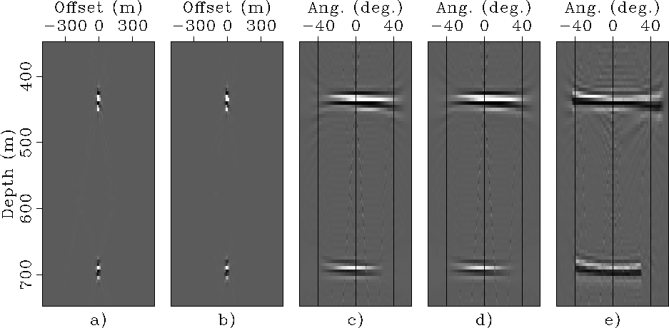
Figure ![[*]](http://sepwww.stanford.edu/latex2html/cross_ref_motif.gif) shows the SODCIGs and the Angle Domain Common Image Gathers (ADCIGs)
obtained by migrating the data sets shown in
Figures
shows the SODCIGs and the Angle Domain Common Image Gathers (ADCIGs)
obtained by migrating the data sets shown in
Figures ![[*]](http://sepwww.stanford.edu/latex2html/cross_ref_motif.gif) and
and ![[*]](http://sepwww.stanford.edu/latex2html/cross_ref_motif.gif) ,
and compares these ADCIGs with the ADCIG
(Figure
,
and compares these ADCIGs with the ADCIG
(Figure ![[*]](http://sepwww.stanford.edu/latex2html/cross_ref_motif.gif) e)
computed from the
SODCIG used as initial condition for modeling.
The ADCIGs show the same kinematics (all three of them are flat),
though the amplitudes in the ADCIGs obtained by
migrating the data modeled by the proposed method
is lower at wide aperture angles.
This difference is likely to be related to the Jacobian
of imaging, similarly to the phenomenon analyzed
by Sava et al. (2004) for downward-continuation migration and modeling.
It warrants further investigations.
e)
computed from the
SODCIG used as initial condition for modeling.
The ADCIGs show the same kinematics (all three of them are flat),
though the amplitudes in the ADCIGs obtained by
migrating the data modeled by the proposed method
is lower at wide aperture angles.
This difference is likely to be related to the Jacobian
of imaging, similarly to the phenomenon analyzed
by Sava et al. (2004) for downward-continuation migration and modeling.
It warrants further investigations.
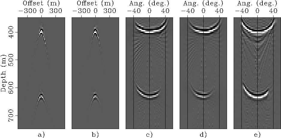
Figure ![[*]](http://sepwww.stanford.edu/latex2html/cross_ref_motif.gif) shows the SODCIGs and the ADCIGs
obtained by migrating the data sets shown in
Figures
shows the SODCIGs and the ADCIGs
obtained by migrating the data sets shown in
Figures ![[*]](http://sepwww.stanford.edu/latex2html/cross_ref_motif.gif) and
and ![[*]](http://sepwww.stanford.edu/latex2html/cross_ref_motif.gif) with a migration velocity too slow by 10%.
The last panel
(Figure
with a migration velocity too slow by 10%.
The last panel
(Figure ![[*]](http://sepwww.stanford.edu/latex2html/cross_ref_motif.gif) e)
shows the ADCIG
computed from
the prestack image obtained by source-receiver migration
of the original 100-shots data set
with a migration velocity too slow by 10%.
The residual moveouts caused by the velocity error are the
same for the ADCIG obtained
by migrating the data modeled starting from an isolated SODCIG
and
by migrating the original data set.
e)
shows the ADCIG
computed from
the prestack image obtained by source-receiver migration
of the original 100-shots data set
with a migration velocity too slow by 10%.
The residual moveouts caused by the velocity error are the
same for the ADCIG obtained
by migrating the data modeled starting from an isolated SODCIG
and
by migrating the original data set.
Mig-Angs-INF-overn
Figure 6
SODCIGs and ADCIGs computed
from the data shown in
Figures ![[*]](http://sepwww.stanford.edu/latex2html/cross_ref_motif.gif) and
and ![[*]](http://sepwww.stanford.edu/latex2html/cross_ref_motif.gif) :
SODCIG from ''flat-reflector'' data (panel a),
SODCIG from ''dipping-reflector'' data (panel b),
ADCIG from ''flat-reflector'' data (panel c),
ADCIG from ''dipping-reflector'' data (panel d),
ADCIG computed from the SODCIG used as initial condition for modeling (panel e).
:
SODCIG from ''flat-reflector'' data (panel a),
SODCIG from ''dipping-reflector'' data (panel b),
ADCIG from ''flat-reflector'' data (panel c),
ADCIG from ''dipping-reflector'' data (panel d),
ADCIG computed from the SODCIG used as initial condition for modeling (panel e).


Mig-Angs-INF-SLOW-overn
Figure 7
SODCIGs and ADCIGs computed
from the data shown in
Figures ![[*]](http://sepwww.stanford.edu/latex2html/cross_ref_motif.gif) and
and ![[*]](http://sepwww.stanford.edu/latex2html/cross_ref_motif.gif) and migrated with a velocity too slow by 10%:
SODCIG from ''flat-reflector'' data (panel a),
SODCIG from ''dipping-reflector'' data (panel b),
ADCIG from ''flat-reflector'' data (panel c),
ADCIG from ''dipping-reflector'' data (panel d),
ADCIG computed by a source-receiver migration
of the original 100-shots data set
with a velocity too slow by 10% (panel e).
and migrated with a velocity too slow by 10%:
SODCIG from ''flat-reflector'' data (panel a),
SODCIG from ''dipping-reflector'' data (panel b),
ADCIG from ''flat-reflector'' data (panel c),
ADCIG from ''dipping-reflector'' data (panel d),
ADCIG computed by a source-receiver migration
of the original 100-shots data set
with a velocity too slow by 10% (panel e).


Next: Cost-efficient prestack exploding-reflector modeling
Up: Prestack exploding reflector modeling
Previous: Modeling of an isolated
Stanford Exploration Project
4/5/2006


![\begin{eqnarray}
\lefteqn{\widebar{I}_{i}\left(z_\xi,x_\xi,h_\xi\right)}
\nonumb...
...\xi';
\right)
\ast
I\left(z_\xi',x_\xi^{i},h_\xi'\right)
\right].\end{eqnarray}](img24.gif)
![[*]](http://sepwww.stanford.edu/latex2html/cross_ref_motif.gif) shows the SODCIGs and the Angle Domain Common Image Gathers (ADCIGs)
obtained by migrating the data sets shown in
Figures
shows the SODCIGs and the Angle Domain Common Image Gathers (ADCIGs)
obtained by migrating the data sets shown in
Figures ![[*]](http://sepwww.stanford.edu/latex2html/cross_ref_motif.gif) and
and ![[*]](http://sepwww.stanford.edu/latex2html/cross_ref_motif.gif) ,
and compares these ADCIGs with the ADCIG
(Figure
,
and compares these ADCIGs with the ADCIG
(Figure ![[*]](http://sepwww.stanford.edu/latex2html/cross_ref_motif.gif) e)
computed from the
SODCIG used as initial condition for modeling.
The ADCIGs show the same kinematics (all three of them are flat),
though the amplitudes in the ADCIGs obtained by
migrating the data modeled by the proposed method
is lower at wide aperture angles.
This difference is likely to be related to the Jacobian
of imaging, similarly to the phenomenon analyzed
by Sava et al. (2004) for downward-continuation migration and modeling.
It warrants further investigations.
e)
computed from the
SODCIG used as initial condition for modeling.
The ADCIGs show the same kinematics (all three of them are flat),
though the amplitudes in the ADCIGs obtained by
migrating the data modeled by the proposed method
is lower at wide aperture angles.
This difference is likely to be related to the Jacobian
of imaging, similarly to the phenomenon analyzed
by Sava et al. (2004) for downward-continuation migration and modeling.
It warrants further investigations.
![[*]](http://sepwww.stanford.edu/latex2html/cross_ref_motif.gif) shows the SODCIGs and the ADCIGs
obtained by migrating the data sets shown in
Figures
shows the SODCIGs and the ADCIGs
obtained by migrating the data sets shown in
Figures ![[*]](http://sepwww.stanford.edu/latex2html/cross_ref_motif.gif) and
and ![[*]](http://sepwww.stanford.edu/latex2html/cross_ref_motif.gif) with a migration velocity too slow by 10%.
The last panel
(Figure
with a migration velocity too slow by 10%.
The last panel
(Figure ![[*]](http://sepwww.stanford.edu/latex2html/cross_ref_motif.gif) e)
shows the ADCIG
computed from
the prestack image obtained by source-receiver migration
of the original 100-shots data set
with a migration velocity too slow by 10%.
The residual moveouts caused by the velocity error are the
same for the ADCIG obtained
by migrating the data modeled starting from an isolated SODCIG
and
by migrating the original data set.
e)
shows the ADCIG
computed from
the prestack image obtained by source-receiver migration
of the original 100-shots data set
with a migration velocity too slow by 10%.
The residual moveouts caused by the velocity error are the
same for the ADCIG obtained
by migrating the data modeled starting from an isolated SODCIG
and
by migrating the original data set.

![[*]](http://sepwww.stanford.edu/latex2html/cross_ref_motif.gif) and
and ![[*]](http://sepwww.stanford.edu/latex2html/cross_ref_motif.gif) :
SODCIG from ''flat-reflector'' data (panel a),
SODCIG from ''dipping-reflector'' data (panel b),
ADCIG from ''flat-reflector'' data (panel c),
ADCIG from ''dipping-reflector'' data (panel d),
ADCIG computed from the SODCIG used as initial condition for modeling (panel e).
:
SODCIG from ''flat-reflector'' data (panel a),
SODCIG from ''dipping-reflector'' data (panel b),
ADCIG from ''flat-reflector'' data (panel c),
ADCIG from ''dipping-reflector'' data (panel d),
ADCIG computed from the SODCIG used as initial condition for modeling (panel e).

![[*]](http://sepwww.stanford.edu/latex2html/cross_ref_motif.gif) and
and ![[*]](http://sepwww.stanford.edu/latex2html/cross_ref_motif.gif) and migrated with a velocity too slow by 10%:
SODCIG from ''flat-reflector'' data (panel a),
SODCIG from ''dipping-reflector'' data (panel b),
ADCIG from ''flat-reflector'' data (panel c),
ADCIG from ''dipping-reflector'' data (panel d),
ADCIG computed by a source-receiver migration
of the original 100-shots data set
with a velocity too slow by 10% (panel e).
and migrated with a velocity too slow by 10%:
SODCIG from ''flat-reflector'' data (panel a),
SODCIG from ''dipping-reflector'' data (panel b),
ADCIG from ''flat-reflector'' data (panel c),
ADCIG from ''dipping-reflector'' data (panel d),
ADCIG computed by a source-receiver migration
of the original 100-shots data set
with a velocity too slow by 10% (panel e).