


Next: [2] Scalar wave equation
Up: wave propagator and its
Previous: wave propagator and its
Based on inverse theory, the characterization of seismic wave propagation is important for parameter estimation. Here I use the acoustic wave equation with two elastic parameters -- bulk modulus and density -- to model seismic wave propagation in a geological medium, though we know that this is a simplification.
| 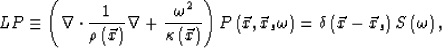 |
(1) |
where  is the bulk modulus and
  is the density. Both parameters vary horizontally as well as vertically.
  is the acoustic pressure wave field, and
  is the monochromatic source function.
We can carry out the full waveform inversion with equation (1). Tarantola (1984) gave a detailed theoretical framework. Pratt and Hicks (1998) discussed in detail how to implement seismic waveform inversion in the frequency domain.
Now I introduce a background model which is so close to the true model that we can neglect the second and higher-order reflection and transmission effects caused by the interaction between the incident wave and the scattering potential. The background wavefield obeys the following equation:
is the monochromatic source function.
We can carry out the full waveform inversion with equation (1). Tarantola (1984) gave a detailed theoretical framework. Pratt and Hicks (1998) discussed in detail how to implement seismic waveform inversion in the frequency domain.
Now I introduce a background model which is so close to the true model that we can neglect the second and higher-order reflection and transmission effects caused by the interaction between the incident wave and the scattering potential. The background wavefield obeys the following equation:
| 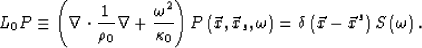 |
(2) |
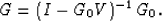
With the definition V=L-L0, the identity  becomes
if we associate G with A and G0 with B.
And equation (3) is further rearranged to
|  |
(4) |
Performing a Taylor expansion on the right term of equation (4) yields
| ![\begin{displaymath}
G=\left[\sum\limits_{j=0}^{\infty}\left( G_{0}V\right)^{j}\right] G_{0} .\end{displaymath}](img9.gif) |
(5) |
Equation (3) is called the Lippmann-Schwinger equationClayton and Stolt (1981). Clearly, if  , equation (5) depicts second and higher-order scattering terms of wave propagation, which are neglected. The linearized propagator characterizes only the first scattering of wave propagation. That is,
This is the Born approximation, the physical meaning of which is clearly demonstrated by equations (5) and (6).
From 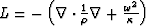 and
and 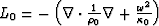 , the scattering potential V is defined as follows:
|  |
|
| |
| |
| (7) |
where  and
and  ;
;  and
and  .Therefore the linearized synthetic wave field is composed of two parts: one is the background wave field described by the background Green's function; the other is the scattering wavefield caused by the scattering potential V.
According to equation (3), the total wave field is written as
.Therefore the linearized synthetic wave field is composed of two parts: one is the background wave field described by the background Green's function; the other is the scattering wavefield caused by the scattering potential V.
According to equation (3), the total wave field is written as
|  |
(8) |
and the scattering wavefield after the Born approximation from equation (6) is
|  |
(9) |
Next: [2] Scalar wave equation
Up: wave propagator and its
Previous: wave propagator and its
Stanford Exploration Project
11/1/2005