


The time domain stacking shown in equation 5 that is implied
by correlating field data with equation 3 can be
explored by considering two transmission wavefields, ![]() and
and ![]() , from individual sources. When placed randomly
on the field record with wait-times
, from individual sources. When placed randomly
on the field record with wait-times ![]() and
and ![]()
| (6) |
| |
(7) |
Redefine A and B as the impulse response of the earth, Ie, convolved with source functions, F which now contain their phase delays. As such, the cross-terms of equation 7 are
| |
(8) |
The inclusion of these cross-terms in the correlation output produces a data volume
![]()
Figure ![[*]](http://sepwww.stanford.edu/latex2html/cross_ref_motif.gif) shows the effect of the cross terms expanded in
equation 8. The figure is directly analogous to
Figure , though with two important differences. First,
there are overlapping source function-reflection pairs. Second, the
direct arrivals are spaced randomly along the time axis rather than
engineering them to lie at the first sample of one of the short
subsections. The second source arrives at the receiver before the
reflection from the first source. The third source is randomly placed
at the far end of the trace. The traces on the right are zoomed versions of
their counterparts to the left. The result desired by a passive
seismologist trying to produce a zero-offset trace from R,
bottom trace Figure , can not be produced. The middle trace
was correlated in the Fourier domain and transformed back to time.
The bottom trace was computed by stacking eight windows from the input
before correlation. The difference between the two output traces
is not from reordering the summation for the Fourier
transform in equation 5. Actually, this is the aliasing of
the autocorrelation result itself. Both methods produce the wrong
result at almost all times. They are however correct and identical at
one location: zero-lag.
shows the effect of the cross terms expanded in
equation 8. The figure is directly analogous to
Figure , though with two important differences. First,
there are overlapping source function-reflection pairs. Second, the
direct arrivals are spaced randomly along the time axis rather than
engineering them to lie at the first sample of one of the short
subsections. The second source arrives at the receiver before the
reflection from the first source. The third source is randomly placed
at the far end of the trace. The traces on the right are zoomed versions of
their counterparts to the left. The result desired by a passive
seismologist trying to produce a zero-offset trace from R,
bottom trace Figure , can not be produced. The middle trace
was correlated in the Fourier domain and transformed back to time.
The bottom trace was computed by stacking eight windows from the input
before correlation. The difference between the two output traces
is not from reordering the summation for the Fourier
transform in equation 5. Actually, this is the aliasing of
the autocorrelation result itself. Both methods produce the wrong
result at almost all times. They are however correct and identical at
one location: zero-lag.
|
freq2
Figure 2 Right panel is 32x zoom of left. (top) Idealized signal of three identical subsurface sources. First two direct-reflection pairs overlap. (middle) Autocorrelation. (bottom) Autocorrelation performed after stacking 8 constituent windows. Zero values are padded on the bottom trace to facilitate plotting. | 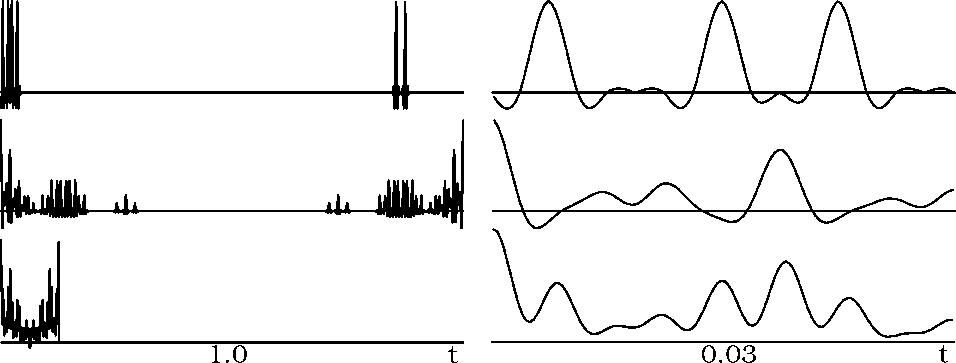 |


Figure shows a more complicated example of the
effective summation of source terms during the Fourier transform. The
first two panels are individual transmission wavefields from sources
at the left side of the model and just to the right of the center of
the model. Notice that the wavefields have been carefully windowed to
assure that the minimum traveltime for the two wavefields
is the same. The model is a constant velocity medium with two
diffractors in the center. The right panel is the sum of 225 similar
sources covering the bottom of the velocity model. Summing the many
shots has created a zero-offset data volume that could be migrated
with a planewave migration algorithm. Cross-correlating this data to
produce shot-gathers produces several dozen flat plane-waves and only
the faintest hint of a ringing train of diffraction hyperbolas.
![]() due to processing Tf rather than the individual
due to processing Tf rather than the individual
![]() records.
records.
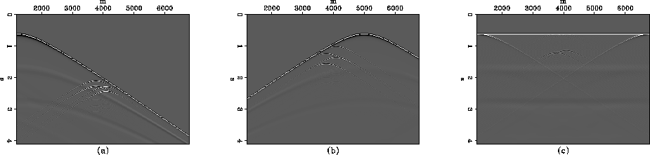 |
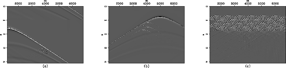
Figure mimics Figure
directly without having taken care to align the direct arrivals to the
same time sample. The summation of all 225 wavefields gives the
result on the right. Cross-correlating this data to produce shot-gathers
makes a very messy plot.
 |