


 |
(40) | |
| (41) | ||
| (42) |
The expressions for the derivatives of the slowness function with respect to the perturbation parameters depend on the particular form chosen to approximate the slowness function. Appendix C derives these derivative for the VTI group slowness function approximation expressed in equation 6, which I used for the numerical experiments shown in this paper.
The partial derivatives of the RMO function ![]() are directly derived from the partial derivatives
of
are directly derived from the partial derivatives
of ![]() , taking into account
that for flat reflectors only the vertical velocity
component VV
influences the image depth of normal incidence.
The derivatives of
, taking into account
that for flat reflectors only the vertical velocity
component VV
influences the image depth of normal incidence.
The derivatives of ![]() can thus be written as follows:
can thus be written as follows:
| |
(43) | |
| (44) | ||
| (45) |
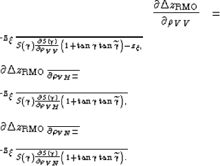
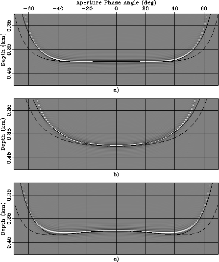
![[*]](http://sepwww.stanford.edu/latex2html/cross_ref_motif.gif) and
show examples of the application of the generalized
RMO functions expressed
in equations 44-46.
As in
Figures - ,
I show the ADCIGs for three different anisotropic rock types,
but, differently from the previous figures, not for the isotropic case.
The order of the rock types is the same as in
Figures - ;
that is: panels a) correspond to Taylor Sand,
panels b) to Mesa Clay Shale, and
panels c) to GreenLight River Shale.
Furthermore, as in
Figures - ,
one figure (Figure )
shows the ADCIG obtained with a smaller perturbation
than the ADCIGs shown in the other figure
(Figure ).
The ADCIGs shown in Figure
were obtained by performing isotropic migration
on the synthetic data modeled assuming anisotropic velocity.
The ADCIGs shown in Figure
were computed by scaling by .25 the parameter perturbations used
to compute Figure .
The lines superimposed onto the images are the RMO functions
computed by using
the correct values for
and
show examples of the application of the generalized
RMO functions expressed
in equations 44-46.
As in
Figures - ,
I show the ADCIGs for three different anisotropic rock types,
but, differently from the previous figures, not for the isotropic case.
The order of the rock types is the same as in
Figures - ;
that is: panels a) correspond to Taylor Sand,
panels b) to Mesa Clay Shale, and
panels c) to GreenLight River Shale.
Furthermore, as in
Figures - ,
one figure (Figure )
shows the ADCIG obtained with a smaller perturbation
than the ADCIGs shown in the other figure
(Figure ).
The ADCIGs shown in Figure
were obtained by performing isotropic migration
on the synthetic data modeled assuming anisotropic velocity.
The ADCIGs shown in Figure
were computed by scaling by .25 the parameter perturbations used
to compute Figure .
The lines superimposed onto the images are the RMO functions
computed by using
the correct values for
The predicted RMO functions accurately track the actual RMO functions
when the parameter perturbations are sufficiently
small to be within the range of accuracy of the
linearization at the basis of the derivation of
equation 40 (Figure ).
But even when the perturbations are large
(Figure ) and
cause a substantial RMO (up to 30% of the reflector depth)
the predicted RMO functions are excellent approximations
of the actual RMO functions.
The RMO functions associated with the two strongly unelliptical rocks (Taylor Sand and GreenLight River Shale) exhibit a characteristic oscillatory behavior; the events at narrow-aperture angles are imaged deeper than the normal incidence event, whereas the events at wide-aperture angles are imaged shallower. This oscillatory behavior is well predicted by the analytical RMO function introduced in equations 44-46.
In contrast,
the approximation of the group angles with the phase angles
(dashed lines in the figures)
seriously deteriorates the accuracy of the predicted RMO functions.
Notice that, in contrast with the uniform perturbation case
illustrated in
Figures - ,
the dashed lines are different among the panels,
because the derivatives
of the slowness function with respect to
the perturbation parameters depend on the anisotropic parameters
of the background medium.
 |
 |
.
The anisotropic data were modeled assuming
three rock types:
a) Taylor Sand, b) Mesa Clay Shale,
and
c) GreenLight River Shale.
Superimposed onto the images are the RMO functions
computed using equation 40.
The solid line was computed when


