|
8-1
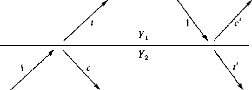
Figure 1 Waves incident, reflected c, and transmitted t at an interface. |  |
Consider two halfspaces (deep ocean on top of earth, for example). If a wave of unit amplitude is incident onto the boundary, there is a transmitted wave of amplitude t and a reflected wave of amplitude c as depicted in Figure 1.
|
8-1
Figure 1 Waves incident, reflected c, and transmitted t at an interface. |  |
A very simple relationship exists between t and c. The wave amplitudes have a physical meaning of something like pressure, material displacement, traction, or tangential electric or magnetic fields. These physical variables must be the same value on either side of the boundary. This means the transmitted wave must equal the sum of the incident plus reflected waves.
| |
(1) | |
| (2) |
The reflection coefficient c may be positive or negative so the transmission coefficient t may be greater than unity. It may seem surprising that t can be greater than unity. This does not violate any physical laws. At the seashore we see waves approaching the shore and they get larger as they arrive. Energy is not determined by wave height alone. Energy is equal to the squared wave amplitude multiplied by a proportionality factor Y depending upon the medium in which the wave is measured. If we denote the factor of the top medium by Y1 and the bottom by Y2, then the statement that the energy before incidence equals the energy after incidence is
| |
(3) |
 |
||
| (4) |
In acoustics the up- and downgoing wave variables may be normalized to either pressure or velocity. When they measure velocity, the scale factor multiplying velocity squared is called the impedance I. When they measure pressure, the scale factor is called the admittance Y.
The wave c' which reflects when energy is incident from the other side is obtained from (4) if Y1 and Y2 are interchanged. Thus
| |
(5) |
A perfectly reflecting interface is one which does not allow energy through. This comes about not only when t = 0 or c = -1, but also when t = 2 or c = +1. To see this, note that on the left in Figure 1
 |
||
| (6) |
Equation (6) says that 100 percent of the incident energy is transmitted when Y1 = Y2, but the percentage of transmission is very small when Y1 and Y2 are very different.
Ordinarily there are two kinds of variables used to describe waves, and both of these can be continuous at a material discontinuity. One is a scalar like pressure, tension, voltage, potential, stress, or temperature. The other is a vector which we use the vertical component. Examples of the latter are velocity, stretch, electric current, dislacement, and heat flow. Occasionally a wave variable is a tensor. When a boundary condition is the vanishing of one of the motion components, then the boundary is often said to be rigid. When it is the pressure or potential which vanishes, then the boundary is often said to be free. Rigid and free boundaries reflect waves with unit magnitude reflection coefficients.
A goal here is to establish fundamental mathematical properties of waves in layers while minimizing specialization to any particular physical type of waves. Each physical problem has its own differential equations. These equations are Fourier transformed over x and y leading to coupled ordinary differential equations in depth z. This analytical process is explained in more detail in FGDP. The next step is an eigenvector analysis that relates the physical variables to our abstract up- and down-going waves U and D. In order to better understand boundary conditions we will examine one concrete example, acoustic waves.
In acoustics we have pressure P and vertical component of parcel velocity W (not to be confused with wave velocity v). The acoustic pressure P is the sum of U and D. Vertical velocity W obviously changes sign when the z axis changes sign (interchange of up and down) and that accounts for the minus sign in the definition of W. (The eigenvector analysis provides us with the scaling factor Y.)
| |
(7) | |
| (8) |
 |
(9) | |
| (10) |
For sound waves in the ocean, the sea surface is nearly a perfect reflector because of the great contrast between air and water. If this interface is idealized to a perfect reflector, then it is a free surface. Since the pressure vanishes on a free surface, we have D = -U at the surface so the reflection coefficient is -1 as shown in Figure 2.
|
8-2
Figure 2 A waveform R(Z) reflecting at the surface of the sea. Pressure equal to U + D vanishes at the surface. The vertical velocity of the surface is proportional to D - U. Theoretically, waves are observed by measuring W at the surface. |  |
In principle we should measure velocity W at the water surface. In practice, we generally measure pressure P a few meters below the free surface.
The pressure normally vanishes at the sea surface, but if we wish to initiate an impulsive disturbance, the pressure may momentarily take on some other value, say 1. This 1 denotes a constant function of frequency which is an impulsive function of time at t=0. Ensuing waves are depicted in Figure 3 where the upcoming wave -R(Z) is a consequence of both the downgoing 1 and the downgoing +R(Z). The vertical component of velocity W of the sea surface due to the source and to the resulting acoustic wave is D - U = 1 + 2R(Z).
|
8-3
Figure 3 An initial downgoing disturbance 1 results in a later upgoing reflected wave -R(Z) which reflects back down as R(Z). The pressure at the surface is D + U = 1 + R - R = 1. |  |