Next: Inversion Results
Up: Solving the Forward Modeling
Previous: Forward modeling examples
The next step is to develop a procedure for back-projecting the residual wavefield. I use a waveform injection approach based on equation 33 that is the adjoint operation of extracting data from the wavefield at acquisition depth. An initially zero-valued wavefield is propagated backwards from the farthest receiver toward the source point. As the wavefield reaches each successive receiver location, the residual at that point is injected into the global wavefield and extrapolated to the next step. This process is repeated for all receivers back to the final step closest to the source point. Note that the one-way formulation precludes back-projection of wavefield interactions occurring at a distance farther than the current extrapolation step. (This is the equivalent to an inability to propagate a turning wave upward to the surface in downward continuation.)
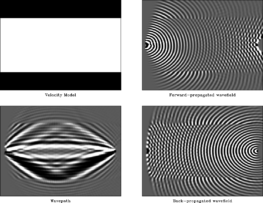
Calculating the gradient term in equation 9 is possible after specifying the forward and back-propagation modeling operations. Figure 9 presents an example of a gradient vector for a source and receiver pair separated by 4 km over a mirrored half-space velocity model (upper left panel).
wavepath
Figure 9 Wavepath example following Woodward (1992). Top left: Half-space velocity model used for synthetic tests. Top right: Forward-propagated wavefield. Bottom right: Back-projected wavefield for a single receiver at 4km offset from source point. Bottom left: Wavepath formed by multiplying wavefields in top and bottom right panels.


The upper right panel shows a monochromatic wavefield propagated forwards from the source point, while the lower right panel shows the wavefield back-propagated from the farthest receiver. The multiplication of these two wavefields is shown in the lower left panel. Woodward (1992), who discusses a similar experiment, terms the result in the lower left "a wavepath" - or the monochromatic analog of a ray-path in the infinite-frequency approximation. Note that the similarity between the wavepath in figure 9 and that of Woodward (1992), whose approach is based on a Rytov approximation.
Next: Inversion Results
Up: Solving the Forward Modeling
Previous: Forward modeling examples
Stanford Exploration Project
1/16/2007