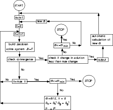
The actual program has been coded for a two-dimensional system, but can easily be extended to three dimensions, as the equations have shown. All equations are solved implicitly for the pore pressure P, the gas saturation Sg and the hydrate saturation Sh at each grid point with the Newton-Raphson method using a Cartesian grid system. A flow chart of the code can be seen in Figure 4.
The time is denoted by n, the number of Newton iterations by it, and
the time steps by ![]() .
Each new
.
Each new ![]() is calculated
automatically based on the
following relationship Aziz (1995):
is calculated
automatically based on the
following relationship Aziz (1995):
 |
(30) |
The desired change of either pore pressure P or saturations Sg and Sh
over ![]() is given by
is given by ![]() , the actual change by
, the actual change by ![]() and
and
![]() is a tuning factor with values between zero and unity. Usually,
is a tuning factor with values between zero and unity. Usually,
![]() has the same value for all grid blocks, but different values for the
different variables (in this case, pressure P, gas and hydrate saturation
Sg and Sh). So a different
has the same value for all grid blocks, but different values for the
different variables (in this case, pressure P, gas and hydrate saturation
Sg and Sh). So a different ![]() is calculated for each
variable and the minimum is used for the subsequent time step.
is calculated for each
variable and the minimum is used for the subsequent time step.
 |
Initially, the system is characterized by a given pore pressure, temperature, gas and hydrate saturation. Perturbation of the pressure at time t=0 or an initial system, which is not in equilibrium, will initialize fluid-flow through the system. The boundary conditions depend on the initial system, and assume either constant pressure boundary at z=0 and no-flow boundaries everywhere else, or no-flow boundaries everywhere.
The code is still in a test phase. As of now, it is working for only two-phase flow and such small hydrate saturation that neither hydrate growth nor dissociation can occur. It is still unstable and non-converging for hydrate saturations bigger than 0.01. Additional work is required to correct this problem.
I conducted a simple test on the functionality of the code for at least two-phase fluid flow with the third, solid hydrate phase being approximately zero. The initial system consisted of a no-flow boundary setup of water over gas with a negligible small hydrate saturation everywhere. The initial pore pressure was comparable to hydrostatic pressure, and the temperature was chosen so that neither hydrate growth nor decomposition could be expected for the pore pressure range. The density difference of gas and water, the pressure gradient and the effect of gravity result in a fluid flow stimulation in which the gas migrates upward and the water travels down.
The grid system is a 10x10 system, each grid block having dimensions of
10 m x 10 m. The top of the grid system is at about 1000 m depth. The grid
blocks within the first 40 m are filled with 100% water, the last 60 m
are filled with 100% gas. To avoid any instabilities resulting from
a vanishing third
flow equation (hydrate equation), a constant hydrate
saturation of 0.001 was assumed throughout the system. The temperature
was chosen to be 10 degrees, and the initial pore pressure followed the
relation Pij= 1000 kg/cm * 9.81 m/s2 * zij. The viscosities were
assumed to be constant with ![]() cp and
cp and ![]() cp. The
relative permeabilities were simply expressed by
cp. The
relative permeabilities were simply expressed by ![]() and
and ![]() . The densities were assumed to be slightly
compressible with
. The densities were assumed to be slightly
compressible with ![]() and
and ![]() .
The absolute permeability was a random permeability field with values
between 10 mD and 10000 mD for each grid block.
.
The absolute permeability was a random permeability field with values
between 10 mD and 10000 mD for each grid block.
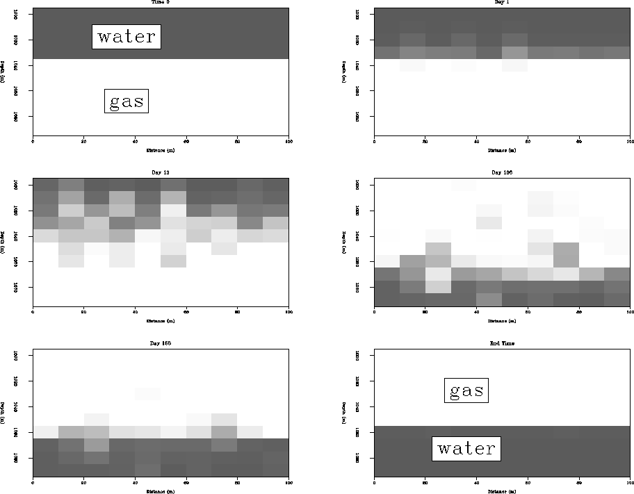
Figure 5 shows the gas saturation results of the fluid-flow initialized by the instable gas-water system. 100 % gas saturation is displayed as white, 0 % as black. At time 0, the water is above the gas and fluid flow is stimulated. After 1 day, gas and water have started to migrate depending on low and high permeabilities in the different grid blocks. Following the permeability pattern, the two fluids begin to mix. After 155 days, the two phases have nearly equilibrized and finally they reach their equilibrium state with gas above water. As soon as this equilibrium state is reached, there is no more flow through the system.
 |
The test shows that the code appears to work correctly for at least a two-phase fluid flow. More work is still required to improve upon the incorporation of a third-phase with more than 0.001 saturation everywhere.