

Next: Summary of the algorithm
Up: Calculating the slowness error
Previous: Model parameterization by spline
After tracing rays and representing the slowness field
with spline coefficients,
the object function we want to minimize
in the least squares sense is
|  |
(41) |
where S is the spline function shown in (![[*]](http://sepwww.stanford.edu/latex2html/cross_ref_motif.gif) ),
and
),
and  is a vector of spline coefficients.
I used the conjugate gradient algorithm to solve
the least squares problem (
is a vector of spline coefficients.
I used the conjugate gradient algorithm to solve
the least squares problem (![[*]](http://sepwww.stanford.edu/latex2html/cross_ref_motif.gif) ).
In using this algorithm, we do not need to construct
the operator L in a matrix form, which is generally huge in size.
Since summing slowness along the ray paths is
the forward operation and putting the traveltime error along
the ray paths is the adjoint of it,
we only need to store the ray paths
that correspond to nonzero components of the operator L.
).
In using this algorithm, we do not need to construct
the operator L in a matrix form, which is generally huge in size.
Since summing slowness along the ray paths is
the forward operation and putting the traveltime error along
the ray paths is the adjoint of it,
we only need to store the ray paths
that correspond to nonzero components of the operator L.
After finding  for the measured traveltime
error
  , the slowness error
  is
obtained from (
is
obtained from (![[*]](http://sepwww.stanford.edu/latex2html/cross_ref_motif.gif) ).
Figure
).
Figure ![[*]](http://sepwww.stanford.edu/latex2html/cross_ref_motif.gif) shows the slowness field updated
by the least-squares inversion of
shows the slowness field updated
by the least-squares inversion of  .Comparing it to the true velocity model Figure
 ![[*]](http://sepwww.stanford.edu/latex2html/cross_ref_motif.gif) ,
we can see that the low-frequency component of the slowness field
was found very easily even in one iteration.
,
we can see that the low-frequency component of the slowness field
was found very easily even in one iteration.
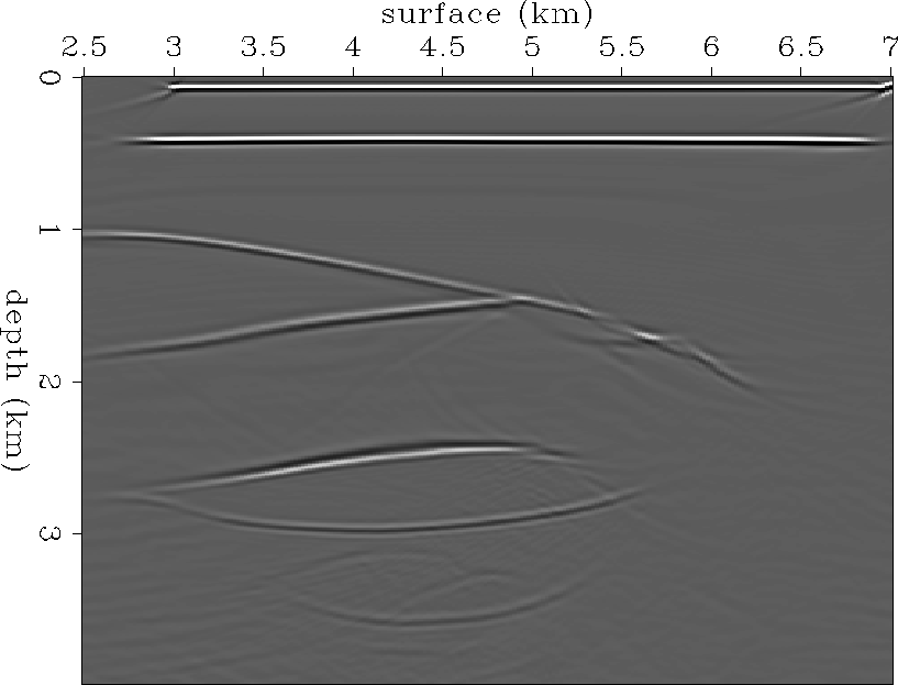
Figure ![[*]](http://sepwww.stanford.edu/latex2html/cross_ref_motif.gif) is a stacked image after planewave
synthesis imaging that synthesized 31 different incidence angles,
from -30 to +30 degrees, at the surface,
using the updated slowness model (Figure
is a stacked image after planewave
synthesis imaging that synthesized 31 different incidence angles,
from -30 to +30 degrees, at the surface,
using the updated slowness model (Figure ![[*]](http://sepwww.stanford.edu/latex2html/cross_ref_motif.gif) ).
Most of the reflectors are located closer to the real position
than that of the images obtained using the initial reference model.
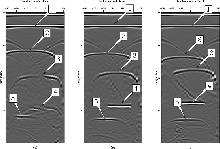
And CSL gathers (Figure
).
Most of the reflectors are located closer to the real position
than that of the images obtained using the initial reference model.
And CSL gathers (Figure ![[*]](http://sepwww.stanford.edu/latex2html/cross_ref_motif.gif) ) show
that most of the reflectors are almost lined up horizontally.
) show
that most of the reflectors are almost lined up horizontally.
synvel-iter1
Figure 16 Velocity model updated by adding  , which was calculated
by inverting
  , to the initial guess w. This corresponds to
one iteration of the traveltime tomography inversion.


 pws-syn-iter1
Figure 17 Stacked image after planewave synthesis imaging that synthesized
31 different incidence angles, from -30 to +30 degrees, at the surface.
For imaging, the updated velocity model (Figure ![[*]](http://sepwww.stanford.edu/latex2html/cross_ref_motif.gif) )
was used.
)
was used.


 crp-iter1
Figure 18 Three CSL gathers at (a) 3 km, (b) 3.5 km, and (c) 4 km
from the prestack image cube that was obtained by
synthesizing plane waves at the surface using the updated velocity model
(Figure ![[*]](http://sepwww.stanford.edu/latex2html/cross_ref_motif.gif) ).
).


Next: Summary of the algorithm
Up: Calculating the slowness error
Previous: Model parameterization by spline
Stanford Exploration Project
2/5/2001
![[*]](http://sepwww.stanford.edu/latex2html/cross_ref_motif.gif) ),
and
),
and ![[*]](http://sepwww.stanford.edu/latex2html/cross_ref_motif.gif) ).
In using this algorithm, we do not need to construct
the operator L in a matrix form, which is generally huge in size.
Since summing slowness along the ray paths is
the forward operation and putting the traveltime error along
the ray paths is the adjoint of it,
we only need to store the ray paths
that correspond to nonzero components of the operator L.
).
In using this algorithm, we do not need to construct
the operator L in a matrix form, which is generally huge in size.
Since summing slowness along the ray paths is
the forward operation and putting the traveltime error along
the ray paths is the adjoint of it,
we only need to store the ray paths
that correspond to nonzero components of the operator L.
![]() for the measured traveltime
error
for the measured traveltime
error ![]() , the slowness error
, the slowness error ![]() is
obtained from (
is
obtained from (![[*]](http://sepwww.stanford.edu/latex2html/cross_ref_motif.gif) ).
Figure
).
Figure ![[*]](http://sepwww.stanford.edu/latex2html/cross_ref_motif.gif) shows the slowness field updated
by the least-squares inversion of
shows the slowness field updated
by the least-squares inversion of ![]() .Comparing it to the true velocity model Figure
.Comparing it to the true velocity model Figure ![[*]](http://sepwww.stanford.edu/latex2html/cross_ref_motif.gif) ,
we can see that the low-frequency component of the slowness field
was found very easily even in one iteration.
,
we can see that the low-frequency component of the slowness field
was found very easily even in one iteration.
![[*]](http://sepwww.stanford.edu/latex2html/cross_ref_motif.gif) is a stacked image after planewave
synthesis imaging that synthesized 31 different incidence angles,
from -30 to +30 degrees, at the surface,
using the updated slowness model (Figure
is a stacked image after planewave
synthesis imaging that synthesized 31 different incidence angles,
from -30 to +30 degrees, at the surface,
using the updated slowness model (Figure ![[*]](http://sepwww.stanford.edu/latex2html/cross_ref_motif.gif) ).
Most of the reflectors are located closer to the real position
than that of the images obtained using the initial reference model.
And CSL gathers (Figure
).
Most of the reflectors are located closer to the real position
than that of the images obtained using the initial reference model.
And CSL gathers (Figure ![[*]](http://sepwww.stanford.edu/latex2html/cross_ref_motif.gif) ) show
that most of the reflectors are almost lined up horizontally.
) show
that most of the reflectors are almost lined up horizontally.


![[*]](http://sepwww.stanford.edu/latex2html/cross_ref_motif.gif) )
was used.
)
was used.

![[*]](http://sepwww.stanford.edu/latex2html/cross_ref_motif.gif) ).
).