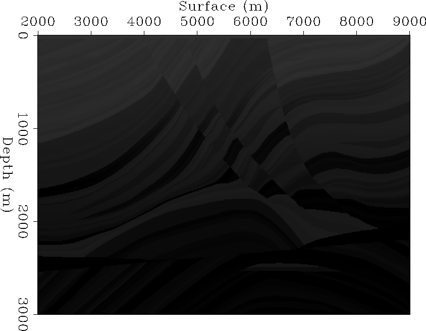
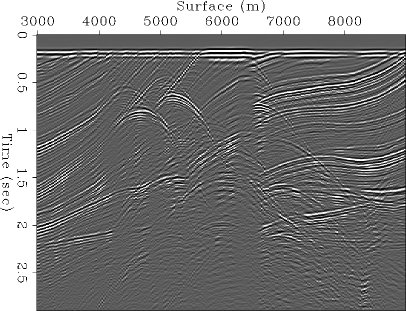
![[*]](http://sepwww.stanford.edu/latex2html/cross_ref_motif.gif) shows the true Marmousi slowness model and
Figure
shows the true Marmousi slowness model and
Figure ![[*]](http://sepwww.stanford.edu/latex2html/cross_ref_motif.gif) shows a near offset section from the dataset.
In this chapter, I used the Marmousi dataset as an example.
shows a near offset section from the dataset.
In this chapter, I used the Marmousi dataset as an example.
The development of seismic stratigraphic interpretation, determination of hydrocarbon potential from amplitude measurements, delineation of reservoirs on expensive offshore tracks and etc., put rather stringent requirements for accuracy of seismic image sections. Processing seismic data by common midpoint (CMP) geometry fails to produce sections that meet the stringent requirements of present day exploration technology.
Prestack depth migration utilizes accurate wave-equation and has long been recognized as the one of the most accurate methods of imaging for areas that are geologically complicated. Another imaging method that follows the wave equation correctly without approximation is the imaging of a stack that is based on wavefront reconstruction, which is often called controlled illumination or plane wave synthesis imaging. Huygens' principle of superposition permits the synthesis of arbitrarily-shaped downward propagating wavefronts from many spherical wavefronts. The idea of synthesizing an areal seismic source from individual shot records is not new. Imaging or processing based on wavefront synthesis has been considered since 1970s. Taner 1976 proposed synthesizing plane wave sources at the surface by stacking traces in a common receiver gather. Claerbout 1976 proposed target-oriented wavefront synthesis as a robust migration scheme through regions of strong lateral velocity variation. Schultz and Claerbout 1978 presented the wave stack concept that is fundamental to the wavefront synthesis and explained how to use it for velocity analysis by synthesizing slanted plane waves. Recently, Rietveld et al. 1992 presented a successful application of the wavefront synthesis method to the well-known Marmousi data set.
In this chapter I show how to apply the imaging method by wavefront synthesis along with the theoretical background and some examples. And I also show how to construct a common incidence angle image section for a given target reflector or for each subsurface point, which provides a fundamental framework for tomographic velocity estimation (chapter 4) and angle-dependent reflectivity recovery (chapter 5), respectively.
A well known testbed for the issues involved in prestack imaging and velocity estimation is the ``Marmousi'' dataset. The dataset was originally created by the Institute Français du Pétrole as a test of velocity inversion methods. It was distributed as a ``blind test'' dataset. The participants in the trial were given a synthetic seismic dataset and two well logs. They then attempted to invert the data to obtain a velocity model. The results of this blind test are described in Versteeg and Grau 1990.
After the blind test was complete, the true velocity model was
published. The Marmousi model is a realistic model
of the subsurface based on the geology of a field in offshore
Angola. It has become a popular testbed for migration algorithms.
Figure ![[*]](http://sepwww.stanford.edu/latex2html/cross_ref_motif.gif) shows the true Marmousi slowness model and
Figure
shows the true Marmousi slowness model and
Figure ![[*]](http://sepwww.stanford.edu/latex2html/cross_ref_motif.gif) shows a near offset section from the dataset.
In this chapter, I used the Marmousi dataset as an example.
shows a near offset section from the dataset.
In this chapter, I used the Marmousi dataset as an example.
 |
 |