

Next: ANTIALIASING
Up: Fomel & Biondi: Azimuth
Previous: Introduction
Azimuth moveout in the time-and-space domain is a three-dimensional
integral operator Fomel and Biondi (1995a). Change (substitution) of the
integrable variables as a method of integral simplification is well
known in classic calculus. In the case of AMO, a convenient choice of
the parameters of integration is of particular value because of the
complicated shape of the operator aperture.
amox12
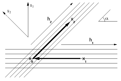
Figure 1 Schematic geometry
of AMO and the transformed coordinate system.

In order to simplify the form of the AMO operator, thus reducing the
cost of its computation, we propose the following substitution of
variables. Let  be the input offset azimuth, and
  be the output offset azimuth with respect to the midpoint coordinate
system. Draw one axis (y1) perpendicular to the direction of
 , and the other axis (y2) perpendicular to
 . This defines a non-orthogonal coordinate system on the
midpoint plane (Figure 1). The transformation of variables,
written in the matrix form, is
| ![\begin{displaymath}
\left[
\begin{array}
{c}
y_1 \\
y_2 \\
\end{array} \...
...
\; \left[
\begin{array}
{c}
x \\
y \end{array} \right]\;,\end{displaymath}](img3.gif) |
(1) |
where x and y are the Cartesian coordinates of a midpoint in the
original coordinate system. The Jacobian of transformation
(1) is simply
 , where
  is the angle of
azimuth rotation. Assuming that
  is greater than zero,
transformation (1) defines a spatially invariant
rotational squeezing of the midpoint space. The special case of
 equal to zero corresponds to the two-dimensional version of
AMO, known as offset continuation
Bolondi et al. (1982); Chemingui and Biondi (1994); Fomel (1995), which can be
handled separately.
amotta
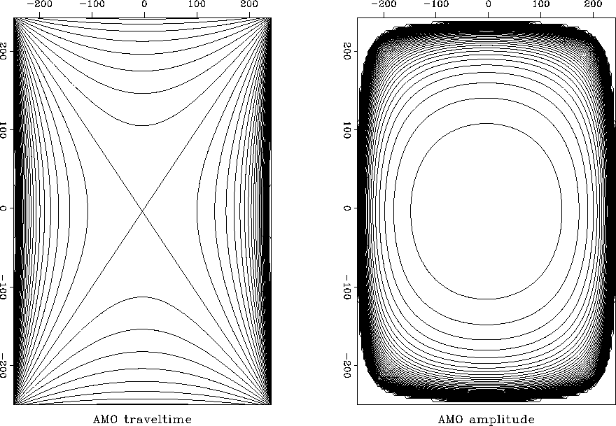
Figure 2
Traveltime and amplitude of the AMO impulse response in the
transformed coordinate system.


The expression for the traveltime of the AMO impulse response (formula (4)
in Biondi and Chemingui (1994a)) transforms to
|  |
(2) |
where  is the midpoint separation in the
transformed coordinate system. In the notation of Biondi and
Chemingui, y1 corresponds to
  , and
y2 corresponds to
  . One can see
that the axes of the transformed coordinate system are now aligned
along the axes of the AMO "saddle". The amplitude equations
Chemingui and Biondi (1995); Fomel and Biondi (1995a) are also simplified (Figure
2). What is more important, the transformation
(1) affects the shape of the AMO aperture.
The aperture limitation (21) from Fomel and Biondi (1995a) transforms after some
heavy algebra to
|  |
(3) |
where
|  |
(4) |
and
|  |
(5) |
The largest possible aperture corresponds to the zero input time (or
zero velocity) and coincides with the interior of a rectangle centered
at  with the sides of the rectangle
equal to
  and
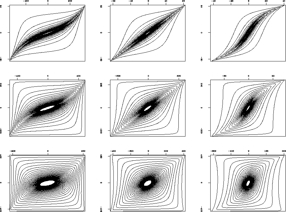
and  . With the time increase, the aperture gradually
decreases in size, and its shape approaches a quasi-elliptical form
(Figure 3).
amoapp
Figure 3 AMO aperture in the
transformed coordinate system as a
function of the input time. The different plots correspond to
different geometries of AMO. From top
to bottom: the angle of azimuth rotation  changes from 10 degrees
(top) to 30 degrees (middle) and 60 degrees (bottom). From left to
right: the ratio of offsets
  changes
from 1/2 (left) to 1 (middle) and 2 (right).


From the computational point of view, it is convenient to evaluate the
right-hand side of inequality (3) outside of the input time
loop and use this inequality to limit the range of times for each
point of the operator.


Next: ANTIALIASING
Up: Fomel & Biondi: Azimuth
Previous: Introduction
Stanford Exploration Project
11/12/1997


![]() be the input offset azimuth, and
be the input offset azimuth, and ![]() be the output offset azimuth with respect to the midpoint coordinate
system. Draw one axis (y1) perpendicular to the direction of
be the output offset azimuth with respect to the midpoint coordinate
system. Draw one axis (y1) perpendicular to the direction of
![]() , and the other axis (y2) perpendicular to
, and the other axis (y2) perpendicular to
![]() . This defines a non-orthogonal coordinate system on the
midpoint plane (Figure 1). The transformation of variables,
written in the matrix form, is
. This defines a non-orthogonal coordinate system on the
midpoint plane (Figure 1). The transformation of variables,
written in the matrix form, is

![]() with the sides of the rectangle
equal to
with the sides of the rectangle
equal to ![]() and
and ![]() . With the time increase, the aperture gradually
decreases in size, and its shape approaches a quasi-elliptical form
(Figure 3).
. With the time increase, the aperture gradually
decreases in size, and its shape approaches a quasi-elliptical form
(Figure 3).
