![[*]](http://sepwww.stanford.edu/latex2html/cross_ref_motif.gif) ,
a discrete form of equation (
,
a discrete form of equation (![[*]](http://sepwww.stanford.edu/latex2html/cross_ref_motif.gif) ) is
) is
For transformation of a wavefield from one datum to another,
as depicted in Figure ![[*]](http://sepwww.stanford.edu/latex2html/cross_ref_motif.gif) ,
a discrete form of equation (
,
a discrete form of equation (![[*]](http://sepwww.stanford.edu/latex2html/cross_ref_motif.gif) ) is
) is
| |
(6) |
| |
(7) |
![]()
![]()
![]()
|
kwed
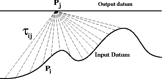
Figure 2 Schematic representation of Kirchhoff upward continuation corresponding to implementation of equation ( ![[*]](http://sepwww.stanford.edu/latex2html/cross_ref_motif.gif) ) or
equation ( ) or
equation (![[*]](http://sepwww.stanford.edu/latex2html/cross_ref_motif.gif) ). Each input trace Pi is filtered,
time shifted according to ). Each input trace Pi is filtered,
time shifted according to |  |
For the special illustrative case of three input traces,
equation (![[*]](http://sepwww.stanford.edu/latex2html/cross_ref_motif.gif) ) can be expressed in matrix form as
) can be expressed in matrix form as
![\begin{displaymath}
\left[
P(x_j,z_j,\omega)
\right]
\;=\;
\left[
\begin{array}...
...,\omega) \\ P(x_{i=3},z_{i=3},\omega) \\ \end{array}\right] ,\end{displaymath}](img32.gif)
![\begin{displaymath}
H \; = \;
\left[
\begin{array}
{cccccc}
\sqrt{-i\omega_1}& &...
... & & &.& \\ & & & & &\sqrt{-i\omega_n} \\ \end{array}\right] .\end{displaymath}](img35.gif)
![\begin{displaymath}
Z_{ij} \; = \;
\left[
\begin{array}
{cccccc}
A_{ij}e^{i\omeg...
... & & & & &A_{ij}e^{i\omega_n \tau_{ij}} \\ \end{array}\right] .\end{displaymath}](img36.gif) |
(8) |
![\begin{displaymath}
\left[
P(x_j,z_j,\omega)
\right]
\;=\;
\left[
\begin{array}...
...,\omega) \\ P(x_{i=3},z_{i=3},\omega) \\ \end{array}\right] .\end{displaymath}](img37.gif) |
(9) |
Equation (![[*]](http://sepwww.stanford.edu/latex2html/cross_ref_motif.gif) ) can be generalized to multiple output traces. For
illustrative purposes, I write down the matrix equation for three input traces
and three output traces. The wavefield at the upper datum is
) can be generalized to multiple output traces. For
illustrative purposes, I write down the matrix equation for three input traces
and three output traces. The wavefield at the upper datum is
![\begin{displaymath}
\left[
\begin{array}
{c}
P(x_{j=1},z_{j=1},\omega) \\ P(x...
...,\omega) \\ P(x_{i=3},z_{i=3},\omega) \\ \end{array}\right] .\end{displaymath}](img38.gif) |
(10) |
![[*]](http://sepwww.stanford.edu/latex2html/cross_ref_motif.gif) ) with ij corresponding to the time shift
) with ij corresponding to the time shift
Equation (![[*]](http://sepwww.stanford.edu/latex2html/cross_ref_motif.gif) ) represents the upward continuation of a wavefield
between two arbitrarily-shaped surfaces.
The downward continuation operator is derived by taking the complex
conjugate transpose of the operator in equation (
) represents the upward continuation of a wavefield
between two arbitrarily-shaped surfaces.
The downward continuation operator is derived by taking the complex
conjugate transpose of the operator in equation (![[*]](http://sepwww.stanford.edu/latex2html/cross_ref_motif.gif) ). This yields
the adjoint operator:
). This yields
the adjoint operator:
![\begin{displaymath}
\left[
\begin{array}
{ccc}
H^*& & \\ &H^*& \\ & &H^* \\...
...2}^* \\ Z_{13}^* & Z_{23}^* & Z_{33}^* \\ \end{array}\right] .\end{displaymath}](img39.gif) |
(11) |
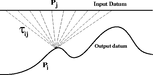
![[*]](http://sepwww.stanford.edu/latex2html/cross_ref_motif.gif) ) is the downward continuation operator
which is depicted in Figure
) is the downward continuation operator
which is depicted in Figure ![[*]](http://sepwww.stanford.edu/latex2html/cross_ref_motif.gif) for one output trace.
for one output trace.
|
kweddown
Figure 3 Schematic representation of Kirchhoff downward continuation corresponding to the operator of equation ( ![[*]](http://sepwww.stanford.edu/latex2html/cross_ref_motif.gif) ). Each input trace Pj
is filtered, time shifted according to ). Each input trace Pj
is filtered, time shifted according to |  |
These matrix representations result in huge, albeit sparse, operator matrices. In the actual computer implementation of Kirchhoff datuming these huge matrix operators are not actually stored. The numerical algorithms apply these linear operators indirectly and much more efficiently.
In order to understand why Kirchhoff datuming is much more efficient than Kirchhoff time migration, it is instructive to look at the kinematics of the two processes. Kirchhoff datuming is performed by summing along a trajectory given by
![]()
![[*]](http://sepwww.stanford.edu/latex2html/cross_ref_motif.gif) a for the simple case of
extrapolation between two level datums.
Time migration is performed by invoking the imaging condition
(setting
a for the simple case of
extrapolation between two level datums.
Time migration is performed by invoking the imaging condition
(setting ![]()
![[*]](http://sepwww.stanford.edu/latex2html/cross_ref_motif.gif) b.
b.
Most of the Kirchhoff datuming results in this dissertation are generated
by implementing equation (![[*]](http://sepwww.stanford.edu/latex2html/cross_ref_motif.gif) ) on Thinking Machine's
massively parallel CM5 (Bevc, 1993). The frequency domain
is computationally attractive because the static time shift
and the convolutional filtering are both efficiently
applied by complex multiplication. This frequency domain implementation
makes Kirchhoff datuming much more efficient than time domain
Kirchhoff migration.
) on Thinking Machine's
massively parallel CM5 (Bevc, 1993). The frequency domain
is computationally attractive because the static time shift
and the convolutional filtering are both efficiently
applied by complex multiplication. This frequency domain implementation
makes Kirchhoff datuming much more efficient than time domain
Kirchhoff migration.
 |
Prestack datuming is performed by using reciprocity to extrapolate shot and receiver gathers (Berryhill, 1984). This can be represented mathematically by the double summation
| |
(12) |
So far, this development has been for constant velocity media. In
variable velocity media, the calculation of the Green's functions
becomes more complicated. The most common way of handling complex
velocity structure with Kirchhoff methods is by
calculating the traveltime shift ![]() using ray tracing or
finite-difference solutions to the eikonal equation.
I choose to use eikonal traveltimes calculated with van Trier and Symes'
(1991) upwind finite-difference algorithm. In Chapter
using ray tracing or
finite-difference solutions to the eikonal equation.
I choose to use eikonal traveltimes calculated with van Trier and Symes'
(1991) upwind finite-difference algorithm. In Chapter ![[*]](http://sepwww.stanford.edu/latex2html/cross_ref_motif.gif) I demonstrate
that this gives excellent results, even for complex velocity models
such as the Marmousi synthetic.
I demonstrate
that this gives excellent results, even for complex velocity models
such as the Marmousi synthetic.