

Next: Marmousi example
Up: Layer-Stripping Kirchhoff migration
Previous: Layer-Stripping Kirchhoff migration
The layer-stripping migration method can be thought of as a hybrid
algorithm that incorporates some of the advantages of recursive
migration with the efficiency of Kirchhoff migration.
I call it semi-recursive because the depth step is much greater than
that used in phase-shift or finite-difference shot-profile migrations.
Because the data are re-synthesized at one or more depth levels
in the subsurface, the method has the added advantage of
implicitly handling multiple arrivals. In each datuming and imaging
step the traveltime tables are single valued, but because the
data are repropagated at every step, the final effect is equivalent
to using multivalued traveltime tables.
This is illustrated by Figures ![[*]](http://sepwww.stanford.edu/latex2html/cross_ref_motif.gif) through
through ![[*]](http://sepwww.stanford.edu/latex2html/cross_ref_motif.gif) ,
which compare recursive migration to standard Kirchhoff migration, and to
the layer-stripping method.
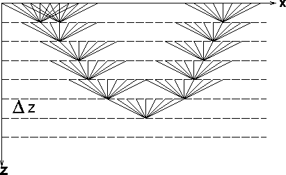
In a recursive method such as shot-profile migration, shots and geophones are
downward continued through each depth level.
Figure
,
which compare recursive migration to standard Kirchhoff migration, and to
the layer-stripping method.
In a recursive method such as shot-profile migration, shots and geophones are
downward continued through each depth level.
Figure ![[*]](http://sepwww.stanford.edu/latex2html/cross_ref_motif.gif) illustrates this for one line of shots or geophones.
It is evident that there are many propagation paths from the surface
to the image point; therefore, multiple arrivals are handled.
The computation is performed for all frequencies.
illustrates this for one line of shots or geophones.
It is evident that there are many propagation paths from the surface
to the image point; therefore, multiple arrivals are handled.
The computation is performed for all frequencies.
By contrast, first-arrival Kirchhoff migration is performed
by summing data over trajectories defined by the propagation paths
illustrated in Figure ![[*]](http://sepwww.stanford.edu/latex2html/cross_ref_motif.gif) . There is only one path linking
each surface position to the image point; therefore, multiple arrivals are
not handled. Although crossing paths are not illustrated here, they can occur.
. There is only one path linking
each surface position to the image point; therefore, multiple arrivals are
not handled. Although crossing paths are not illustrated here, they can occur.
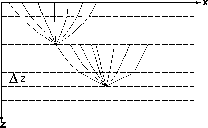
The layer-stripping method is illustrated in Figure ![[*]](http://sepwww.stanford.edu/latex2html/cross_ref_motif.gif) .
It is a combination of Kirchhoff wave-equation datuming
and Kirchhoff migration.
There are multiple propagation paths from the surface
to the image point; therefore, multiple arrivals are handled.
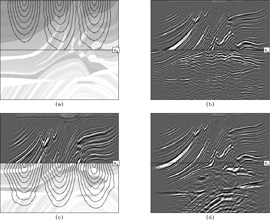
The computation is illustrated for the Marmousi model in Figure
.
It is a combination of Kirchhoff wave-equation datuming
and Kirchhoff migration.
There are multiple propagation paths from the surface
to the image point; therefore, multiple arrivals are handled.
The computation is illustrated for the Marmousi model in Figure ![[*]](http://sepwww.stanford.edu/latex2html/cross_ref_motif.gif) and proceeds as follows:
and proceeds as follows:
- 1.
- Calculation of traveltimes from the surface (Figure
![[*]](http://sepwww.stanford.edu/latex2html/cross_ref_motif.gif) a).
These traveltimes are used to:
a).
These traveltimes are used to:
- Migrate from the surface to some depth level z1 or lower.
- Downward continue to depth level z1
(Figure
![[*]](http://sepwww.stanford.edu/latex2html/cross_ref_motif.gif) b).
b).
- 2.
- Calculation of traveltimes from depth
level z1 (Figure
![[*]](http://sepwww.stanford.edu/latex2html/cross_ref_motif.gif) c).
These traveltimes are used to:
c).
These traveltimes are used to:
- Migrate from depth level z1
(Figure
![[*]](http://sepwww.stanford.edu/latex2html/cross_ref_motif.gif) d).
d).
The depth step of Kirchhoff downward continuation is much larger than the
 used in shot-profile migration. Since
there are multiple paths from the surface to the image point,
multiple arrivals are handled. Because the paths are shorter than
in Figure
 ![[*]](http://sepwww.stanford.edu/latex2html/cross_ref_motif.gif) , first-arrival traveltimes are more likely to
be valid.
, first-arrival traveltimes are more likely to
be valid.
s-g
Figure 8 Propagation paths for shot-profile migration.
A few representative propagation paths from the surface to an
image point for shot-profile migration. There are many paths from
each surface location to the depth point.
|
|  |

kirch
Figure 9 Propagation paths from the surface to an image point for Kirchhoff migration.
There is only one path from each surface location to the depth point.
|
|  |

datum
Figure 10 Propagation paths from the surface to a depth point for layer-stripping
Kirchhoff downward continuation and migration.
Paths traverse shorter distances so they
are less likely to cross, and there are multiple paths to each depth point.
|
|  |
 calc
calc
Figure 11 Illustration of layer-stripping Kirchhoff datuming and migration.
The velocity model is divided into two parts.
(a) Finite-difference traveltimes
are calculated in the upper part of the model.
(b) These traveltimes are used to image the upper portion of the
data and downward continue the wavefield, resynthesizing it at depth
level z1.
(c) Traveltimes are calculated from depth level z1 and
(d) used to image the downward continued wavefield. Movie.
![[*]](http://sepwww.stanford.edu/latex2html/movie.gif)


Next: Marmousi example
Up: Layer-Stripping Kirchhoff migration
Previous: Layer-Stripping Kirchhoff migration
Stanford Exploration Project
2/12/2001
![[*]](http://sepwww.stanford.edu/latex2html/cross_ref_motif.gif) through
through ![[*]](http://sepwww.stanford.edu/latex2html/cross_ref_motif.gif) ,
which compare recursive migration to standard Kirchhoff migration, and to
the layer-stripping method.
In a recursive method such as shot-profile migration, shots and geophones are
downward continued through each depth level.
Figure
,
which compare recursive migration to standard Kirchhoff migration, and to
the layer-stripping method.
In a recursive method such as shot-profile migration, shots and geophones are
downward continued through each depth level.
Figure ![[*]](http://sepwww.stanford.edu/latex2html/cross_ref_motif.gif) illustrates this for one line of shots or geophones.
It is evident that there are many propagation paths from the surface
to the image point; therefore, multiple arrivals are handled.
The computation is performed for all frequencies.
illustrates this for one line of shots or geophones.
It is evident that there are many propagation paths from the surface
to the image point; therefore, multiple arrivals are handled.
The computation is performed for all frequencies.


![[*]](http://sepwww.stanford.edu/latex2html/movie.gif)