 |
 |
 |
 | Delayed-shot migration in TEC coordinates |  |
![[pdf]](icons/pdf.png) |
Next: TEC extrapolation wavenumber
Up: Shragge: 3D imaging in
Previous: Inline delayed-shot migration
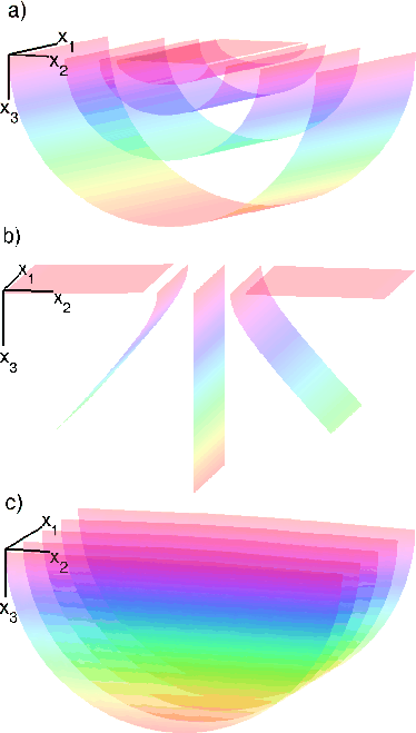
One question to be addressed is what coordinate system geometry optimally conforms to the impulse response of a conical wavefield? I assert that the best geometry is that of the TEC coordinate system shown in Figures 1 and 2. One advantage is that the breadth of the first extrapolation step at the surface allows multiple streamers of a single sail line to be positioned directly on a single mesh. Hence, this geometry is applicable to both narrow- and wide-azimuth acquisition. A second advantage is that one direction of large-angle propagation can be handled by coordinate system tilting, while the other is naturally handled by the ellipticality of the mesh. (Note that the geometry of another natural mesh - cylindrical polar coordinates - would not be a judicious choice for because the geometry permits migration of only single-streamer data and has singular points located on the surface at the first extrapolation step.)
I set up the migration geometry of the elliptical-cylindrical mesh as follows:
-
![$ \xi_3 \in [0,\infty]$](img60.png) is the extrapolation direction, where surfaces of constant
is the extrapolation direction, where surfaces of constant  form concentric elliptical cylinders, shown in Figure 1a.
-
 is the crossline direction, where surfaces of constant
  are folded hyperbolic planes, shown in Figure 1b; and
-
![$ \xi_1 \in [-\infty,\infty]$](img62.png) is the inline direction, where surfaces of constant
is the inline direction, where surfaces of constant  are 2D elliptical coordinate meshes, shown in Figure 1c;
|
|---|
TECgeom
Figure 1. Constant surfaces of the elliptical-cylindrical coordinate system (with zero inline tilt). Cartesian coordinate axes are given by the vector diagram. a) constant surfaces forming confocal elliptical-cylindrical shells that represent the direction of extrapolation direction. b) constant surfaces representing folded hyperbolic planes. c) constant surfaces representing 2D elliptical meshes. NR
|
|---|
![[png]](icons/viewmag.png)
|
|---|
The mapping relationship between the two coordinate systems, adapted from Arfken (1970), is
![$\displaystyle \left[\begin{array}{c} x_1 x_2 x_3 \end{array}\right] = \le...
...m {sinh} \xi_3 \rm {sin} \xi_2 {\rm cos} \theta \end{array}\right],$](img63.png) |
(13) |
where 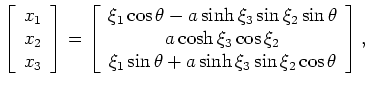 is the inline tilt angle of the coordinate system and parameter
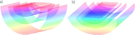
  controls the coordinate system breadth. Panels 2a and 2b show the TEC coordinate system at
  and
and  tilt angles, respectively.
|
|---|
TEC
Figure 2. Four extrapolation steps in of an TEC coordinate system, where the and coordinate axes are oriented in the inline and crossline directions, respectively. a) 0 tilt angle. b) 25 tilt angle. NR tilt angle. b) 25 tilt angle. NR
|
|---|
|
|
|---|
Subsections
|
|
|
|
| Delayed-shot migration in TEC coordinates | |
|
Next: TEC extrapolation wavenumber
Up: Shragge: 3D imaging in
Previous: Inline delayed-shot migration
2009-05-05