|
|
|
|
Target-oriented wave-equation inversion: regularization in the reflection angle |
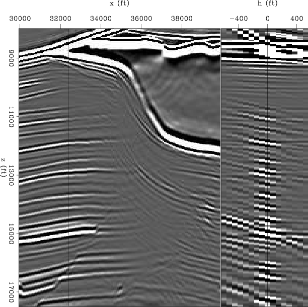
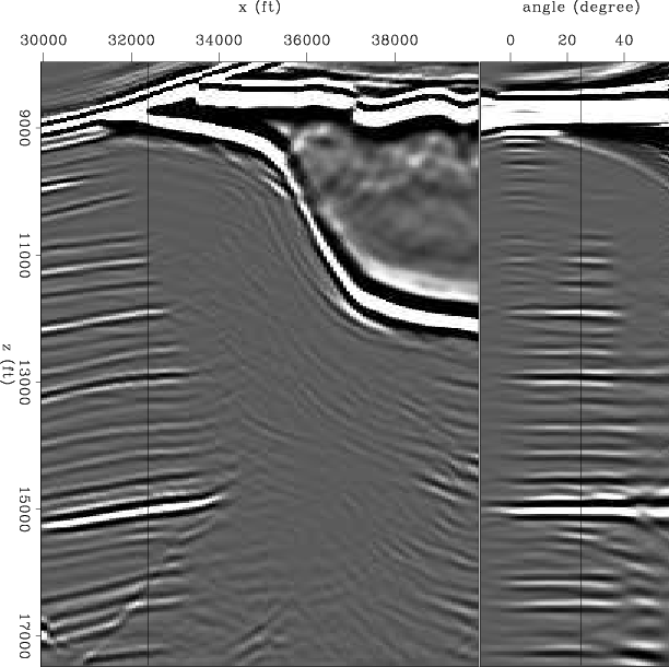
Figures 7 and 8 show the migration result in the subsurface-offset domain and the reflection-angle domain, respectively. The migration in the subsurface-offset domain is the "data", and corresponds to the right hand side of equation 4. The migration at the reflection-angle domain is shown for comparison purposes, since the model space corresponds to the reflection-angle domain.
|
|---|
|
migoff
Figure 7. Sigsbee shot-profile migration(subsurface-offset) using cross-correlation imaging condition. |
|
|
|
|---|
|
migang
Figure 8. Sigsbee shot-profile migration (reflection angle) using cross-correlation imaging condition. |
|
|
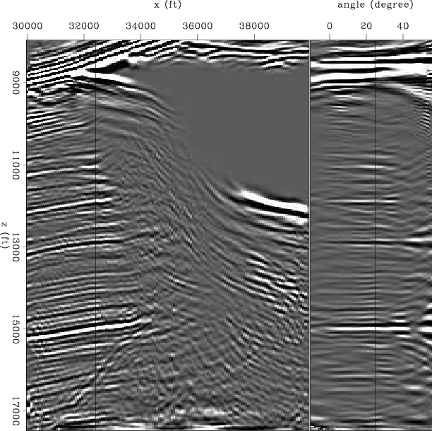
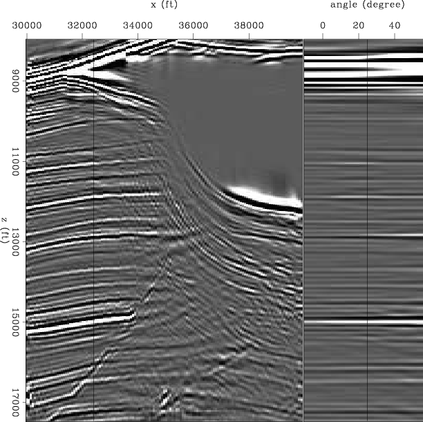
Figures 9 and 10 show the inversion without and with regularization in the reflection-angle domain, respectively (compare to migration in Figure 8). The left panel shows a common angle section (![]() ). The migration shows a big shadow zone below the salt (Figure 8). In the inversion without regularization (Figure 9) the shadow zone has been filled partially but the results are very noisy. The regularized inversion image (Figure 10) gives a better result, less noisy and with some of the reflectors extended into the shadow zone.
). The migration shows a big shadow zone below the salt (Figure 8). In the inversion without regularization (Figure 9) the shadow zone has been filled partially but the results are very noisy. The regularized inversion image (Figure 10) gives a better result, less noisy and with some of the reflectors extended into the shadow zone.
|
|---|
|
invang
Figure 9. Sigsbee inversion without regularization (reflection angle). |
|
|
|
|---|
|
invregang
Figure 10. Sigsbee inversion with regularization (reflection angle). |
|
|
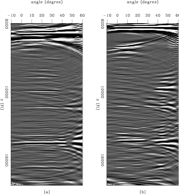
If we look in more detail into the angle gathers (Figures 11, 12, and 13) the effect of the inversion and the regularization can be understood separately. Figure 11 shows angle gathers at three different ![]() coordinate positions
coordinate positions ![]() ,
, ![]() ,
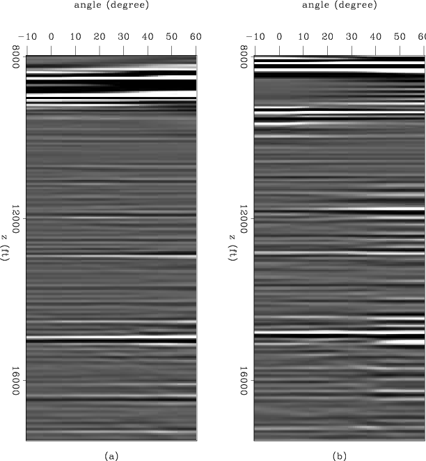
, ![]() . Notice the holes in some of the reflectors, also notice that there are salt related multiple reflections (non-flat events in the angle gathers). After inversion without regularization (Figure 12) some the wholes have being filled but the noise has increase as well as the bandlimited related artifacts off the slant-stack, also the multiples had been increased in amplitude. The inversion with regularization (Figure 13), gives the best result. The wholes have being filled, the noise is reduced, and the far-angle-multiple energy is decreased.
. Notice the holes in some of the reflectors, also notice that there are salt related multiple reflections (non-flat events in the angle gathers). After inversion without regularization (Figure 12) some the wholes have being filled but the noise has increase as well as the bandlimited related artifacts off the slant-stack, also the multiples had been increased in amplitude. The inversion with regularization (Figure 13), gives the best result. The wholes have being filled, the noise is reduced, and the far-angle-multiple energy is decreased.

|
|---|
|
compmigang
Figure 11. Sigsbee migration (reflection angle). Angle gathers at three different |
|
|
|
|---|
|
compinvang
Figure 12. Sigsbee inversion without regularization (reflection angle). Angle gathers at three different |
|
|
|
|---|
|
compinvregang
Figure 13. Sigsbee inversion with regularization (reflection angle). Angle gathers at three different |
|
|
|
|
|
|
Target-oriented wave-equation inversion: regularization in the reflection angle |