Next: Source-Receiver Migration
Up: Preprocessing
Previous: Datuming
In order to choose the key migration parameters such as depth step, number
of frequencies and especially the minimum amount of padding of negative subsurface
offsets needed to accommodate the migration of the multiples, I ran some tests using
common-azimuth migration (, ).
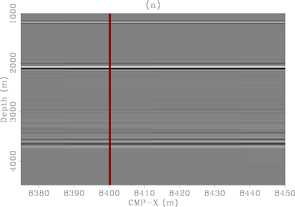
Figure 14 shows
the inline dimensions (CMP and offset) of an SODCIG after common-azimuth
migration. Notice that the multiples have been mapped to the negative
subsurface offsets and to shallower depths, consistent with the results
of Chapter ![[*]](icons/crossref.png) .
.
|
|---|
cam1
Figure 14. Common-azimuth migration. Panel (a) is the migrated inline
section at CMP-Y=662.5 m, zero inline subsurface offset and -25 m crossline
subsurface offset. Panel (b) is the inline subsurface offset gather at CMP-X=8400 m,
CMP-Y=662.5 m and -25 m crossline subsurface offset. Notice in panel (b) how the
multiple migrated towards the negative subsurface offsets.
|
|---|
![[pdf]](icons/pdf.png) ![[png]](icons/viewmag.png)
|
|---|
Next: Source-Receiver Migration
Up: Preprocessing
Previous: Datuming
2007-10-24