|
|
|
|
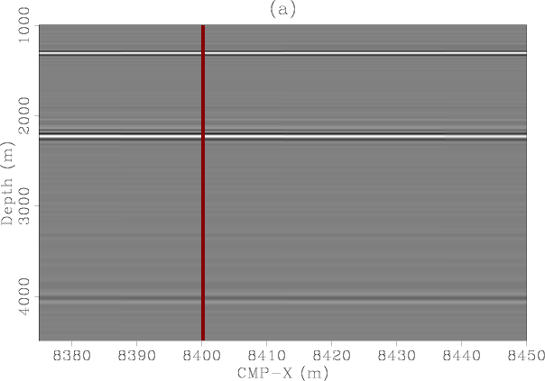
Figure 15 shows the inline dimensions of one SODCIG. Again, note that the multiples migrate to the negative subsurface offsets and are well separated from the primaries, which map around zero subsurface offset.
|
|---|
|
pre3dmig1
Figure 15. Source-receiver migration. Panel (a) is the migrated inline section at CMP-Y=1212.5 m, zero inline subsurface offset and 25 m crossline subsurface offset. Panel (b) is the inline subsurface offset gather taken at CMP-X=8400 m, CMP-Y=1212.5 m and 25 m crossline subsurface offset. Notice again how the multiple migrates toward the negative subsurface offsets. |
|
|
In contrast with the inline direction, the sampling of the crossline offsets and CMPs is very coarse and the results of the migration are not nearly as good. This is illustrated in Figure 16 which shows a cube of crossline CMPs as a function of crossline offset. Although the primaries have been relatively focused toward zero subsurface offset, there is still a lot of energy smearing to both positive and negative crossline subsurface offsets. Even worse, the multiple looks almost as focused as the primaries because of the lack of crossline data and insufficient crossline migration aperture.

|
|---|
|
pre3dmig3
Figure 16. Source-receiver migration. Panel (a) is the migrated crossline section at CMP-X=8450 m, zero inline subsurface offset and zero crossline subsurface offset. Panel (b) is the crossline subsurface offset gather taken at CMP-X=8450 m, CMP-Y=912.5 m and zero inline subsurface offset. |
|
|
Figure 17 shows a zero subsurface-offset cube of the migrated data. The image is good in the inline direction and somewhat noisy in the crossline direction. The large sparsity of the crossline offsets create migration artifacts.

|
|---|
|
pre3dmig2
Figure 17. Source-receiver migration. Panel (a) is the migrated inline section at CMP-Y=912.5 m, zero inline subsurface offset and zero crossline subsurface offset. Panel (b) is the migrated crossline section at CMP-X=8400 m, zero inline subsurface offset and zero crossline subsurface offset. The image in the inline direction is good, but in the crossline direction has artifacts associated to the sparse sampling in that direction. |
|
|
|
|
|
|