

Next: Conclusions
Up: Examples
Previous: CMP gathers
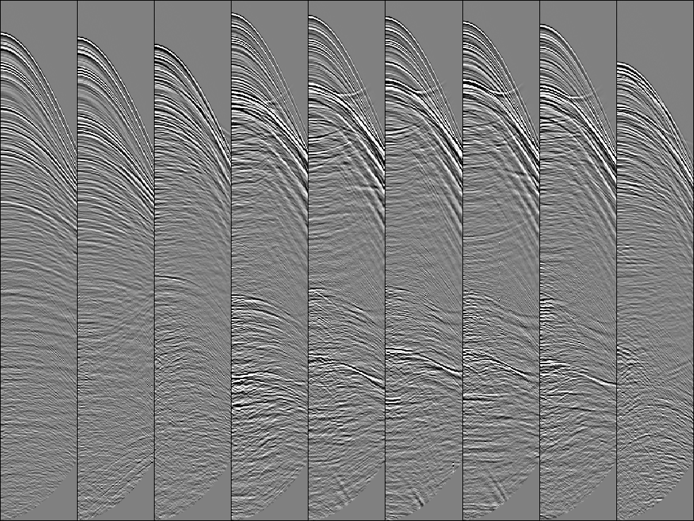
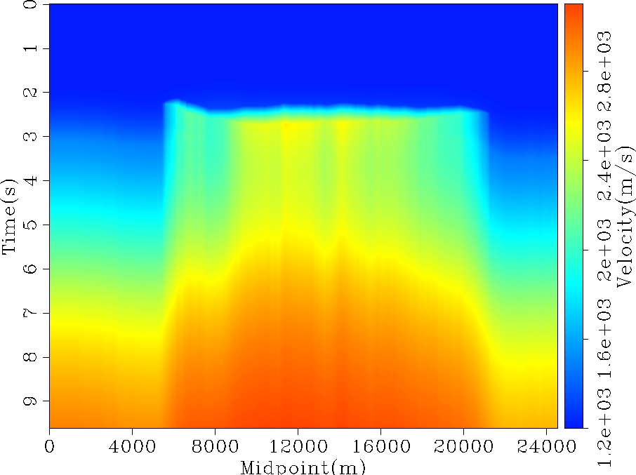
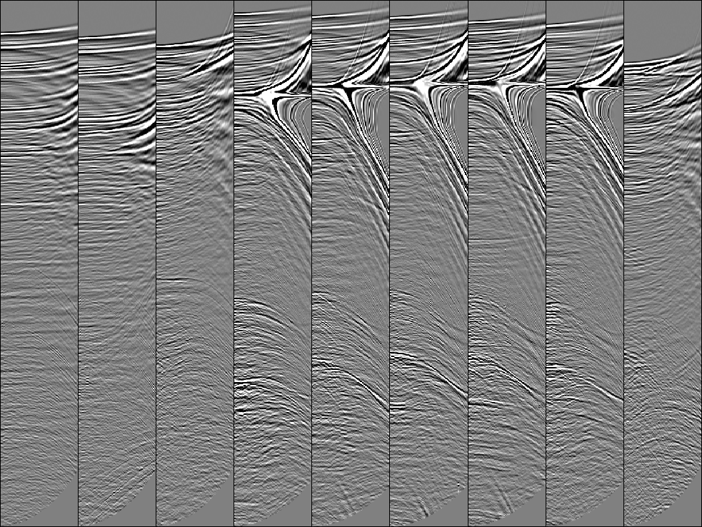
Nine sample CMP gathers are shown in Figure 5. Radon de-multiple pre-processing has been applied but significant multiple energy can still be seen in the bottom half of the gathers. For comparison to the flattening method, conventional processing is first applied. Using the simple velocity field shown in Figure 6, NMO is applied to the gathers and the results are shown in Figure 7. This velocity is obviously not exact but many primaries are almost flat. The data is stretched badly and could benefit from a stretch mute.
v_rms
Figure 6 RMS velocity model.
 compnmo
Figure 7 Same gathers as Figure 5 with NMO applied using the velocity function in Figure 6. This velocity is obviously incorrect in several areas but it does flatten many of the primaries and it does not flatten the multiples.

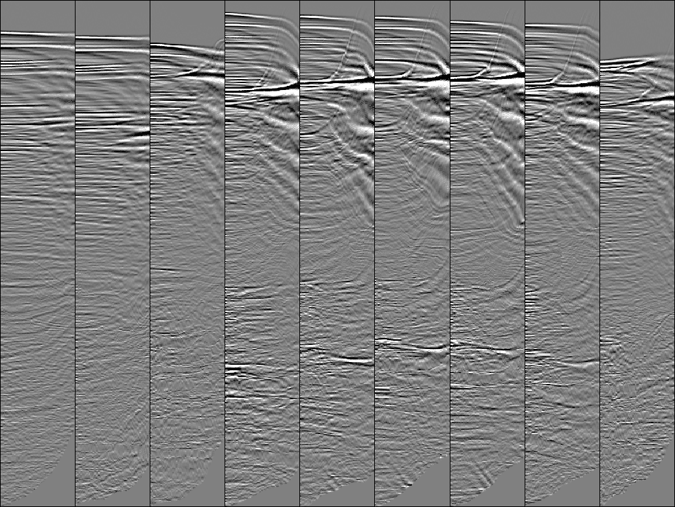
To reduce dip estimation errors, we first apply NMO with a constant velocity of 2000  . Applying NMO with this simple velocity does not require knowing any velocity information at all. Next, the gathers are flattened. The nine flattened gathers are shown in Figure 10. These gathers don't have the same stretching errors as in Figure 7 but events with the strongest amplitude are flattened regardless of whether they are primaries, multiples, or headwaves. Evidence of this can be seen in the lower half where the flattening method has flattened the undesirable multiple energy. At the top of the gathers, the flattening method flattens the gathers significantly better than the NMO in Figure 7.
compcmp
Figure 8 Same gathers as Figure 5 with NMO applied using a constant velocity function, 2000  .
.

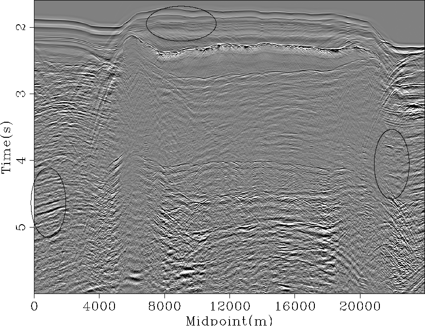
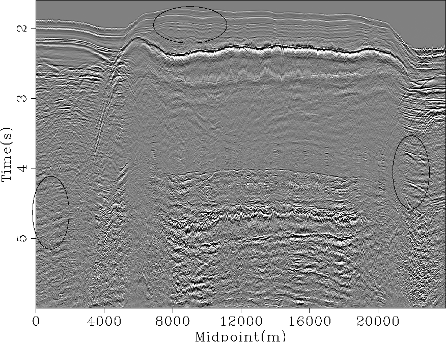
The resulting stacked sections with conventional processing and flattening applied can be seen in Figures 9 and 11, respectively. The flattening method does a better job imaging the diffractions seen in the ellipse at the top of the section. However, in the conventional processing image, the primaries are imaged better in the lower left ellipse. In the ellipse on the lower right, the flattening does a much better job imaging the bright reflections.
stacknmo
Figure 9 Stacked 2D section using the velocity in Figure 6.
 compflat
Figure 10 Flattened version of the gathers in Figure 8.
 stackflat
Figure 11 Stacked 2D section using flattened gathers.

In the stacked section after flattening was applied in Figure 11, there is significant jitter between CMP's. This is because each CMP was flattened independently. We can easily correct this by estimating dip from gather to gather and solve the analytical flattening method in 3D. An adjustable parameter that controls the weight of the flattening between gathers can be added as well.


Next: Conclusions
Up: Examples
Previous: CMP gathers
Stanford Exploration Project
5/23/2004

![]() . Applying NMO with this simple velocity does not require knowing any velocity information at all. Next, the gathers are flattened. The nine flattened gathers are shown in Figure 10. These gathers don't have the same stretching errors as in Figure 7 but events with the strongest amplitude are flattened regardless of whether they are primaries, multiples, or headwaves. Evidence of this can be seen in the lower half where the flattening method has flattened the undesirable multiple energy. At the top of the gathers, the flattening method flattens the gathers significantly better than the NMO in Figure 7.
. Applying NMO with this simple velocity does not require knowing any velocity information at all. Next, the gathers are flattened. The nine flattened gathers are shown in Figure 10. These gathers don't have the same stretching errors as in Figure 7 but events with the strongest amplitude are flattened regardless of whether they are primaries, multiples, or headwaves. Evidence of this can be seen in the lower half where the flattening method has flattened the undesirable multiple energy. At the top of the gathers, the flattening method flattens the gathers significantly better than the NMO in Figure 7.
