

Next: Building the three colormap
Up: Vlad: Image display with
Previous: NTSC and its properties
The input data in this process consists of the luminance and the
chrominance images. Both are stored in real-valued, normalized matrices
(respectively L and C). The output will be a RGB image with
three components: R,G and B, obtained by transforming a NTSC image
composed of the matrices Y, I and Q. The first step is thus transforming L and C into the
NTSC components Y, I and Q through a colormap operator (actually, a
set of three related operators)
The next section will elaborate on the construction of the three
operators. Once the Y, I and Q matrices are obtained, we basically have the color image, but since computer
devices work with RGB, we usually need to transform to RGB with the
equation
| ![\begin{displaymath}
\left[
\matrix { R \cr G \cr B}
\right]
=
\left[
\matr...
...703 }
\right]
\ \
\left[
\matrix { Y \cr I \cr Q}
\right]\end{displaymath}](img1.gif) |
(4) |
before writing the file to disk Kuhn (1996).
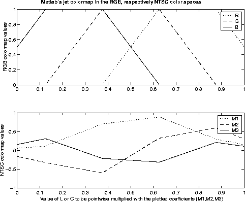
jetcolormap
Figure 1 The main part of the operators M1, M2 and
M3 consists of the transformation from RGB to NTSC of a common colormap


Next: Building the three colormap
Up: Vlad: Image display with
Previous: NTSC and its properties
Stanford Exploration Project
9/18/2001
![\begin{displaymath}
\left[
\matrix { R \cr G \cr B}
\right]
=
\left[
\matr...
...703 }
\right]
\ \
\left[
\matrix { Y \cr I \cr Q}
\right]\end{displaymath}](img1.gif)
![\begin{displaymath}
\left[
\matrix { R \cr G \cr B}
\right]
=
\left[
\matr...
...703 }
\right]
\ \
\left[
\matrix { Y \cr I \cr Q}
\right]\end{displaymath}](img1.gif)
