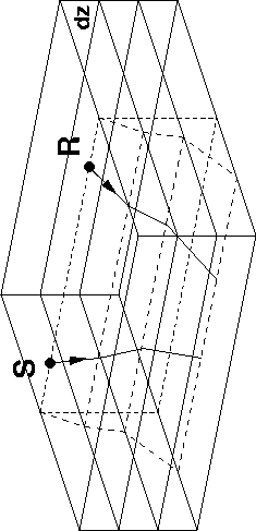
Theory shows that even in a simple 1-D v(z) medium, CAM is not perfectly accurate: the stationary-phase approximation used in the derivation of CAM Biondi and Palacharla (1996) imposes the relation among ray parameters indicated below that constrains rays to keep the same azimuth at each depth step (Figure 1):
| |
(1) |
|
ray-comaz
Figure 1 Ray geometry imposed by common-azimuth constraints: both receiver and source rays keep the same azimuth at each depth step. |  |
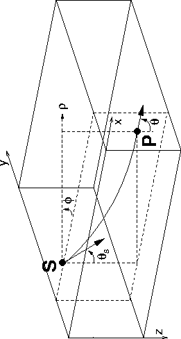
We choose to test the behavior of rays and the accuracy of CAM approximations in a synthetic medium where the velocity varies linearly. In such a medium, ray trajectories can be computed analytically, as well as all ray parameters. Figure 2 illustrates the geometry of the problem. With those notations, ray curvature can be expressed as Aki and Richards (1980):
| (2) |
| (3) |
 |
The ratio ![]() is also the horizontal
component
is also the horizontal
component ![]() of the slowness vector along the ray, which therefore is
also a constant:
of the slowness vector along the ray, which therefore is
also a constant:
| (4) |
After some calculation (see Appendix), the equation of the circle of
radius R passing through point source ![]() with initial incident angle
with initial incident angle
![]() is, in the plane
is, in the plane ![]() :
:
 |
(5) |
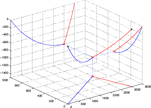
For any given triplet of points (S,P,R), respectively source, image point and receiver locations, there exist only two circles satisfying equation (5) that form the complete ray path. Figures 3 to 5 illustrate such ray paths. We can verify that the projections of the source ray and the receiver ray on the cross-line plane do not coincide in general and therefore break the assumption of azimuth conservation in CAM downward-continuation imposed by relation (1).
|
ray_exmpl1
Figure 3 Example of 3-D analytical ray tracing, with the three projections of both rays on vertical and horizontal planes. Source and receiver location are indicated with solid stars. The reflection point and its three projections are represented by a circle. Offset is 3000m (in-line). Velocity is |  |
|
ray_exmpl2
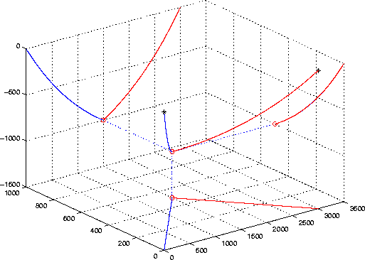
Figure 4 Same geometry as before. The only difference is in the velocity: |  |
|
ray_exmpl3
Figure 5 Velocity law is |  |
However, with too strong a velocity gradient, rays quickly start to overturn (Figure 4). The corresponding reflection cannot be imaged with one-way wave propagation methods, such as CAM and the other wave-equation migration methods we discuss in this paper.