

Next: Angle-domain CIG and velocity
Up: Prucha, et al.: Angle-domain
Previous: Kinematics of Multiarrivals in
In the previous sections we discussed the advantages of
angle-domain CIGs over offset-domain CIGs
when a complex velocity function
induces multipathing and event triplication.
In this section we show how to extract angle-domain CIGs
from downward-continued prestack data.
Recorded 3-D seismic data can be organized
as a function of midpoint coordinates ( )and offset coordinates (
 ).
Prestack data are efficiently downward continued
using the DSR equation in the frequency (
 ) domain.
Furthermore, since we either use 2-D downward continuation
or 3-D common-azimuth downward continuation,
the offset space is restricted to the in-line offset hx,
and thus we express the recorded wavefield as
 ,where z is depth and z=0 indicates data recorded at the surface.
The prestack wavefield at depth is obtained by downward continuing
the recorded data using the DSR,
and is imaged by extracting
the values at zero time
|  |
(1) |
| (2) |
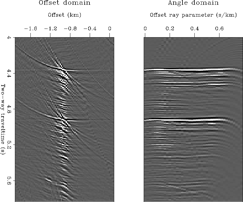
The downward-continuation process
focuses the wavefield towards zero offset
(left panel in Figure 5)
and if the continuation velocity is correct,
a migrated image can be obtained by extracting
the value of the wavefield at zero offset.
However, the zero-offset wavefield has limited
diagnostic information for velocity updating,
and
no information on the amplitude of the reflections
versus reflection angle (AVA).
We therefore perform a slant stack along the offset axis
before imaging and obtain an image as a function
of the offset ray parameter phx,
as
|  |
(3) |
| (4) |
| (5) |
Angle-domain CIGs are subsets of
 at fixed midpoint location.
The right panel in Figure 5
shows the angle-domain CIG gather
corresponding to the downward-continued offset gather shown
in the left panel.
Notice that because in downward-continued offset gathers
the energy is concentrated around zero offset,
the slant stack decomposition does not suffer from
the usual artifacts caused by the boundary conditions.
Strictly speaking,
the CIG gathers obtained by the proposed procedure
are function of the offset ray parameters phx
and not of the aperture angle  .However, phx is linked to
  by the following
simple trigonometric relationship
|  |
(6) |
where  is the geological dip along the in-line
direction and
  is the velocity function.
AVO-hydrate-off-angle
Figure 5 Left: Offset panel after downward continuation. Right: Angle-domain CIG


Next: Angle-domain CIG and velocity
Up: Prucha, et al.: Angle-domain
Previous: Kinematics of Multiarrivals in
Stanford Exploration Project
4/20/1999
![]() )and offset coordinates (
)and offset coordinates (![]() ).
Prestack data are efficiently downward continued
using the DSR equation in the frequency (
).
Prestack data are efficiently downward continued
using the DSR equation in the frequency (![]() ) domain.
Furthermore, since we either use 2-D downward continuation
or 3-D common-azimuth downward continuation,
the offset space is restricted to the in-line offset hx,
and thus we express the recorded wavefield as
) domain.
Furthermore, since we either use 2-D downward continuation
or 3-D common-azimuth downward continuation,
the offset space is restricted to the in-line offset hx,
and thus we express the recorded wavefield as
![]() ,where z is depth and z=0 indicates data recorded at the surface.
,where z is depth and z=0 indicates data recorded at the surface.


![]() .However, phx is linked to
.However, phx is linked to ![]() by the following
simple trigonometric relationship
by the following
simple trigonometric relationship
