|
 |
 |
 | Reverse-time migration using wavefield decomposition |  |
![[pdf]](icons/pdf.png) |
Next: Wavefield decomposition
Up: Taweesintananon: RTM using wavefield
Previous: Origin of RTM artifacts
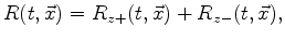
A common method of wavefield decomposition is to obtain wavefields' one-way
components with respect to two orthogonal
directions, i.e. horizontal directions (leftgoing/rightgoing) and
vertical directions (upgoing/downgoing). Hereafter I use the notations
 to represent the downgoing wave component with respect to the
vertical depth axis, and
to represent the downgoing wave component with respect to the
vertical depth axis, and  to represent
the rightgoing wave component with respect to the horizontal space
axis. Note that a downgoing wavefield indicates a wavefield where the vertical direction of propagation is downward with time running forward, whereas a rightgoing wavefield indicates a wavefield where the horizontal direction of propagation is rightward with time running forward.
to represent
the rightgoing wave component with respect to the horizontal space
axis. Note that a downgoing wavefield indicates a wavefield where the vertical direction of propagation is downward with time running forward, whereas a rightgoing wavefield indicates a wavefield where the horizontal direction of propagation is rightward with time running forward.
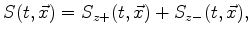
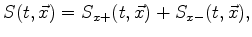
Source and receiver wavefields can be decomposed into their downgoing
and upgoing components as follows (Liu et al., 2007):
 |
(3) |
 |
(4) |
where
 ,
,
 ,
,
 and
and
 are the downgoing and
upgoing source and receiver wavefields, respectively.
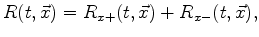
Similarly, they can also be decomposed into their horizontal components as follows:
are the downgoing and
upgoing source and receiver wavefields, respectively.
Similarly, they can also be decomposed into their horizontal components as follows:
 |
(5) |
 |
(6) |
where
 ,
,
 ,
,
 and
and
 are the rightgoing and
leftgoing source and receiver wavefields respectively.
are the rightgoing and
leftgoing source and receiver wavefields respectively.
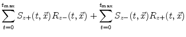
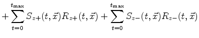
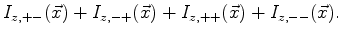
Thus, the conventional imaging condition can be separated into four imaging conditions based on combinations of vertical wavefield components:
The first term is the cross-correlation of the downgoing source and
upgoing receiver wavefields, which is equivalent to the result of
downward continuing migration. The second term is the cross-correlation of the upgoing source and
downgoing receiver wavefields. Thus, the first two terms can represent any reflector that causes vertical backscattering.
The images corresponding to these two terms are caused by backward-scattered events with respect to the vertical axis. The subimages from the remaining two terms can be considered as noise,
which results from vertical forward-scattered events where source and
receiver wavefields are vertically propagating in the same direction. Thus, the last two terms contribute to artifacts in RTM. However, these are related to tomographic information in wave-equation migration velocity
analysis (Almomin et al., 2011).
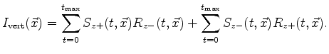
In order to suppress RTM artifacts, the imaging
condition that contains only the first two terms in
Equation 7 (Liu et al., 2007,2011) as
 |
(8) |
This condition might be called
the vertical backscatter-based imaging condition.
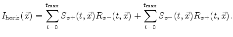
The horizontal backscatter-based imaging condition can be derived in a
similar way. This horizontal imaging condition
contains only cross-correlation of the source and receiver
wavefields that are propagating in horizontally opposite directions:
 |
(9) |
The first term is the cross-correlation of the rightgoing source and
leftgoing receiver wavefields. The second term is the cross-correlation of the leftgoing source and
rightgoing receiver wavefields. Thus, this imaging condition
represents any reflector that causes horizontal backscattering.
To use the benefits of both vertical and horizontal backscatter-based imaging conditions, they are added togather (Liu et al., 2011):
 |
(10) |
This imaging condition might be called the Cartesian backscatter-based imaging condition. Note that the subimages from both vertical and horizontal imaging condition partly overlap, because of the overlap between the vertical and horizontal wavefield components. For example, the wavefield that is moving in any downright direction can be considered to be either downgoing or rightgoing.
In addition, the Cartesian backscatter-based imaging condition described above only involves the decomposition of source and receiver wavefields into their vertical or horizontal components. Thus, some backward-scattered events are indistinguishable from forward-scattered events using only this decomposition scheme. Therefore, the image illumination is reduced. However, Equation 10 produces no forward-scattered artifacts based on Cartesian directions of propagation. Thus, this proposed imaging condition can suppress artifacts in RTM images.
|
|
|
|
| Reverse-time migration using wavefield decomposition | |
|
Next: Wavefield decomposition
Up: Taweesintananon: RTM using wavefield
Previous: Origin of RTM artifacts
2011-05-24