

Next: Conclusion
Up: Sun & Fomel: Fast-marching
Previous: Variational formulation of fast-marching
We implemented TFMES in both 2-D and 3-D cases.
The 3-D constant velocity medium is used as a benchmark test to verify the
accuracy of the new algorithm. We use the same sampling interval in both
the Cartesian and the tetragonal coordinates to make a fair comparison.
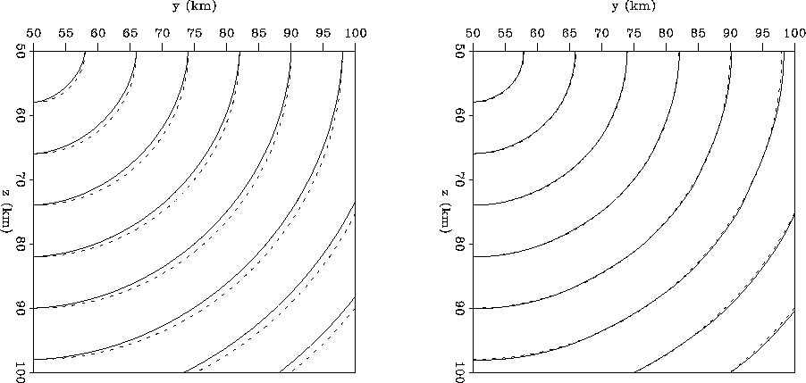
As shown in Figure 7, the Cartesian implementation
tends to over-estimate the traveltime in the diagonal direction, while
the tetragonal result matches the analytical result very accurately.
const3D-comp
Figure 7 Left: Cartesian. Right: tetragonal. Traveltime slice from a 3-D constant velocity model. The source is located at the upper-left corner and the spatial sampling interval is 1km in all the three directions. The dash line represents the analytical solution. The solid line on the left panel stands for the Cartesian implementation and the solid line on the right for the tetragonal case. The Cartesian result has obvious errors in the diagonal direction. The tetragonal result matches the analytical result accurately.


More complex Marmousi and SEG/EAGE saltdome models are used to test its
stability when handling more complex models.
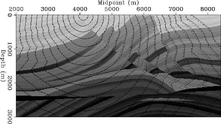
Figure 8 is the test of 2-D Marmousi model. The source
is located on the surface at coordinates (x=4100m, z=0m). In most areas,
the two results match each other. When passing through the complex
structure in the middle, they begin to deviate from each other.
The trigonal result is not as smooth as the Cartesian result. This is
because the trigonal result has six neighboring points instead of four
points in the Cartesian coordinates, which makes it more capable of
simulating complex wavefront. The Cartesian implementation over-estimates
the traveltime compared with the trigonal result, which is similar to the
conclusion reached by Alkhalifah and Fomel
1997.
marm-comp
Figure 8 Traveltime slice of 2-D Marmousi model. The solid line stands for the trigonal result and the dash line for the Cartesian result. The Cartesian implementation tends to over-estimate the traveltime.


Figure 9 and 10
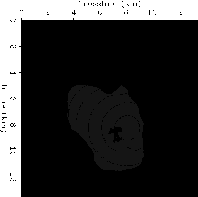
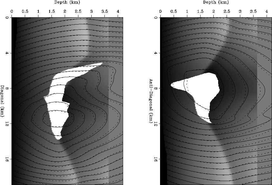
show three traveltime slices from the SEG/EAGE saltdome model. The source is
located at coordinates (x=7200m, y=7320m, z=1680m).
Figure 9 was obtained with a constant depth z=1560m,
while Figure 10 were extracted in the diagonal and
anti-diagonal directions of x-y plane.
salt-depth
Figure 9 Traveltime slice of 3-D SEG/EAGE saltdome model for a constant z=1560m. The solid line represents tetragonal result and the dash line for the Cartesian result. For most part, the Cartesian result tends to over-estimate the traveltime than the tetragonal result.


 salt-diag
Figure 10 Traveltime slices of 3-D SEG/EAGE saltdome model in the diagonal direction. Left: Diagonal direction. Right: Anti-diagonal direction.


Next: Conclusion
Up: Sun & Fomel: Fast-marching
Previous: Variational formulation of fast-marching
Stanford Exploration Project
9/12/2000


