


| (35) |
| (36) |
 |
||
| (37) |
| |
(38) |
| |
(39) |
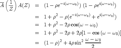
This is called a ``narrow-band filter" because in the Fourier domain
the function is large only in a narrow band of frequencies.
Setting ![]() to half its peak value of
to half its peak value of ![]() ,we find a half-bandwidth of
,we find a half-bandwidth of ![]() .The damping time constant
.The damping time constant ![]() of the damped sinusoid bt
is shown in the exercises following this section
to be
of the damped sinusoid bt
is shown in the exercises following this section
to be ![]() .
.
Naturally we want a real-time function,
so we multiply the filter 1/(1-Z/Zp) times ![]() .The resulting time function is real
because conjugate poles are like the conjugate roots.
The spectrum of the conjugate factor
.The resulting time function is real
because conjugate poles are like the conjugate roots.
The spectrum of the conjugate factor ![]() is like (38), except that
is like (38), except that ![]() is replaced by
is replaced by ![]() .Multiplying the response (38) by itself with
.Multiplying the response (38) by itself with ![]() yields the symmetric function of
yields the symmetric function of ![]() displayed on the right in Figure 9.
displayed on the right in Figure 9.
 |

You might be disappointed if you intend to apply the filter of
Figure 9 as a narrow-band filter.
Notice that the passband is asymmetric
and that it passes the zero frequency.
Equation (38) is symmetric about ![]() ,but taking the product
with its image about
,but taking the product
with its image about ![]() has spoiled the symmetry.
Should we be concerned about this ``edge effect''?
The answer is yes, whenever we handle real data.
For real data,
has spoiled the symmetry.
Should we be concerned about this ``edge effect''?
The answer is yes, whenever we handle real data.
For real data, ![]() is usually small enough.
Recall that
is usually small enough.
Recall that
![]() .Consider a pole at a particular
.Consider a pole at a particular ![]() :decreasing
:decreasing ![]() pushes
pushes ![]() towards zero,
which is where a pole and its mate at negative frequency
create the asymmetrical response shown in Figure 9.
towards zero,
which is where a pole and its mate at negative frequency
create the asymmetrical response shown in Figure 9.
So in practice we might like to add a zero at zero frequency and at the Nyquist frequency, i.e., (1-Z)(1+Z), as shown in Figure 10.
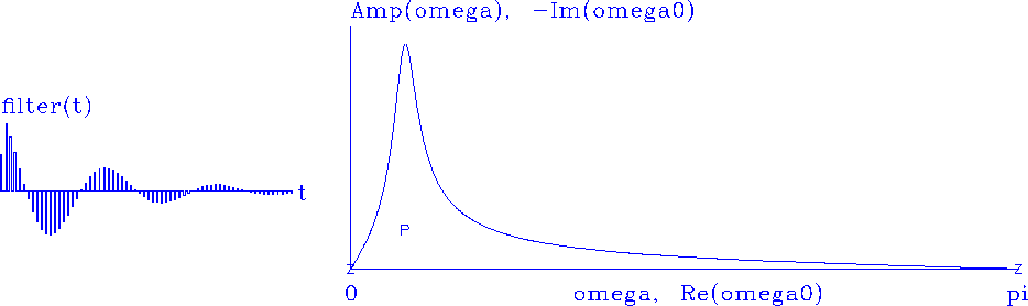 |
Compare Figure 10 and 9. If the time functions were interchanged, could you tell the difference between the figures? There are two ways to distinguish them. The most obvious is that the zero-frequency component is made evident in the time domain by the sum of the filter coefficients (theoretically, F(Z=1)). A more subtle clue is that the first half-cycle of the wave in Figure 10 is shorter than in Figure 9; hence, it contains extra high frequency energy, which we can see in the spectrum.