


The puck() method was designed to be ignorant of side boundaries: it can be applied in a small window and the window moved freely around the data. A strength of the puck() method is that the window can be smaller than a wavelength--it can be merely two traces wide. A sample based on synthetic data is shown in Figures 9 through 11. The synthetic data in 9 mimics a reflection seismic field profile, including one trace that is slightly delayed as if recorded on a patch of unconsolidated soil.
|
puckin
Figure 7 Input synthetic data. | 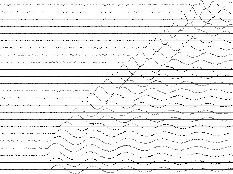 |


Notice a low level of noise in the synthetic data.
Figure 10 shows the residual.
|
residual
Figure 8 Residuals, i.e., an evaluation of Ux +p Ut. | 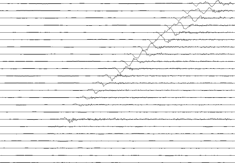 |
The residual is small in the central region of the data; it is large where there is spatial aliasing; and it is large at the transient onset of the signal. The residual is rough because of the noise in the signal, because it is made from derivatives, and because the synthetic data was made by nearest-neighbor interpolation. Notice that the residual is not particularly large for the delayed trace.
Figure 11 shows the dips.
|
puckout
Figure 9 Output values of p are shown by the slope of short line segments. | 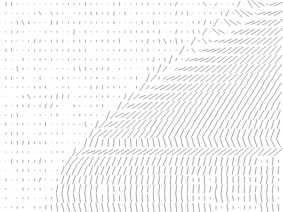 |
The most significant feature of this figure is the sharp localization of the dips surrounding the delayed trace. Other methods based on wave or Fourier concepts might lead us to conclude that the aperture must be large to resolve a wide range of angles. Here we have a narrow aperture (two traces), but the dip can change rapidly and widely.
Subroutine slider() ![[*]](http://sepwww.stanford.edu/latex2html/cross_ref_motif.gif) below shows the code that generated
Figure 9 through 11.
below shows the code that generated
Figure 9 through 11.
# slide a window around on a wall of data measuring coherency, dip, residual
#
subroutine slider( n1,n2, w1,w2, k1,k2, data, coh, pp, res)
integer i1,i2,     n1,n2, w1,w2, k1,k2,                    s1,s2, e1,e2
integer p1,p2                           # number of subwindows is p1*p2
real    data(n1,n2)                     # input
real    res(n1,n2)                      # outputs. math size (n1-1,n2-1)
real    pp(n1,n2), coh(n1,n2)           # outputs defined at pp( 1..p1, 1..p2)
temporary real  count( n1,n2)
temporary real  window(w1,w2), tres(w1-1,w2-1)
call null(      count, n1*n2)
call null(        res, n1*n2)
p2=0; e2=w2; while( e2<=n2) {  p2=p2+1; s2=e2-w2+1
p1=1; e1=w1; while( e1<=n1) {  p1=p1+1; s1=e1-w1+1
        do i1 = 1, w1 {
        do i2 = 1, w2 { window(i1,i2) = data(i1+s1-1,i2+s2-1)
                        }}
        call null(                                         tres, (w1-1)*(w2-1))
        call puck ( w1, w2, window, coh(p1,p2), pp(p1,p2), tres)
        do i1= s1, e1-1 {
        do i2= s2, e2-1 {
                res(  i1,i2) =    res(i1,i2) + tres( i1-s1+1, i2-s2+1)
                count(i1,i2) =  count(i1,i2) + 1.
                }}
        e1=e1+k1            }
        e2=e2+k2            }
do i2= 1, n2-1 {
do i1= 1, n1-1 {        if( count(i1,i2) > 0. )
                                res(i1,i2) = res(i1,i2) / count(i1,i2)
                }}
return; end
A disadvantage of the puck() method
is that the finite-difference operator is susceptible to spatial aliasing
as well as to distortions at spatial frequencies
that are high but not yet aliased.
This suggests a logical step--estimating missing interlaced traces--which
we take up in chapter .
| (32) |
| (33) |
1