

Next: Wavefront healing
Up: LATERAL VELOCITY IN BIGGER
Previous: Lateral shift of the
A second example
of lateral velocity variation
is Figure 22, also taken
from Kjartansson's dissertation.
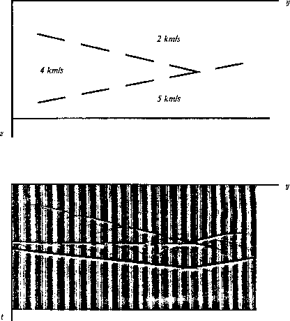
The physical model shown on the inset in Figure 22
is three constant
velocity wedges separated by broken line segments representing reflectors.
westdepthmig
Figure 22
The model in the upper panel was taken from Western Geophysical's
Depth Migration brochure.
The model is not physical because of the segmenting of the interface;
however,
the segments make it a good case for the study of lateral shifts.
The synthetic data is in the lower panel (from Kjartansson).
The phantom diffraction is on the latest arrival just below
the tip of the wedge.

The bottom edge of the model also represents a reflector.
The wavefield in Figure 22
was made using the exploding-reflector calculation,
which Kjartansson regarded as a
reasonable approximation to a zero-offset section.
Notice that under the tip of the 4 km/sec wedge is a
small diffraction on the
bottom horizontal reflector.
Because such a diffraction has nothing to do
with the flat reflector on which it is seen,
it is termed a ``phantom'' diffraction.
Phantom diffractions are not easy to recognize,
but they do occur.
In reality, the ``bright spots'' in Kjartansson's section
were probably phantom diffractions.
It has been reported that phantom diffractions provide a means
of prospecting for small, high-velocity, carbonate reefs.


Next: Wavefront healing
Up: LATERAL VELOCITY IN BIGGER
Previous: Lateral shift of the
Stanford Exploration Project
10/31/1997
