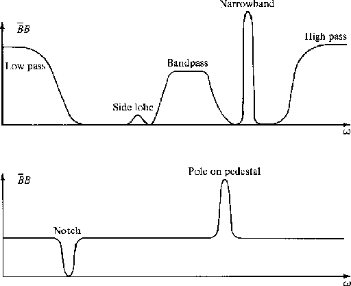
Filters are often used to modify the spectrum of given data.
With input X(Z), filters B(Z), and output Y(Z) we have
Y(Z) = B(Z)X(Z) and the Fourier conjugate
![]() .
Multiplying these two relations together we get
.
Multiplying these two relations together we get
| (25) |
 |
We will have frequent occasion to deal with sinusoidal time functions. A simple way to represent a sinusoid by Z transforms is
| |
(26) |
The time function associated with this Z transform is
![]() , but it is ``turned on'' at t = 0. Actually,
the left-hand side of (26) contains a pole exactly
on the unit circle, so that the series sits on the borderline
between convergence and divergence. This can cause paradoxical
situations
[you could expand (26) so that the sinusoid turns off at t = 0]
which we will avoid by pushing the pole
from the unit circle to a small distance
, but it is ``turned on'' at t = 0. Actually,
the left-hand side of (26) contains a pole exactly
on the unit circle, so that the series sits on the borderline
between convergence and divergence. This can cause paradoxical
situations
[you could expand (26) so that the sinusoid turns off at t = 0]
which we will avoid by pushing the pole
from the unit circle to a small distance ![]() outside
the unit circle. Let
outside
the unit circle. Let ![]() Then define
Then define
 |
||
| (27) |
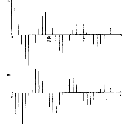
The time function corresponding to B(Z) is zero before
t = 0 and is ![]() after t = 0.
It is a sinusoidal function which decreases gradually with time
according to
after t = 0.
It is a sinusoidal function which decreases gradually with time
according to ![]() .The coefficients are shown in Figure 14.
.The coefficients are shown in Figure 14.
|
2-14
Figure 14 The time function associated with a simple pole just outside the unit circle at |  |
It is intuitively obvious, although we will prove it later, that convolution with the coefficients of (27), which are sketched in Figure 14, is a narrow-banded filtering operation. If the pole is chosen very close to the unit circle, the filter bandpass becomes narrower and the coefficients of B(Z) drop off more and more slowly. To actually perform the convolution it is necessary to truncate, that is, to drop powers of Z beyond a certain practical limit. It turns out that there is a very much cheaper method of narrow-band filtering than convolution with the coefficients of B(Z). This method is polynomial division by A(Z). We have for the output Y(Z)
 |
(28) | |
| (29) |
| |
(30) |
For definiteness, let us suppose the xt and yt vanish before t = 0. Now identify coefficients of successive powers of Z. We get
 |
||
| (31) | ||
| |
(32) |
 |
(33) |
 |
||
so
 |
||
| (34) |
To a good approximation
this function may be thought of as
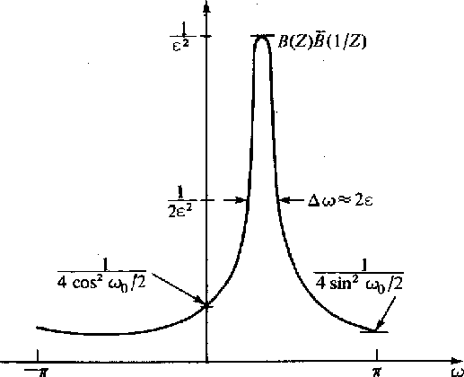
![]() A plot of (34) is shown in Figure 15.
A plot of (34) is shown in Figure 15.
|
2-15
Figure 15 Spectrum associated with a single pole at |  |
Now it should be apparant why this is called
a narrowband filter. It amplifies a vary narrow
band of frequencies and
attenuates all others. The frequency window
of this filter is said to be
![]() in width.
The time window is
in width.
The time window is
![]() ,the damping time constant of the dampend sinusoid bt.
,the damping time constant of the dampend sinusoid bt.
One practical disadvantage of the filter under discussion is that although its input may be a real time series its output will be a complex time series. For many applications a filter with real coefficients may be preferred.
One approach is to follow the filter
![]() by the time-domain, complex conjugate filter
by the time-domain, complex conjugate filter
![]() .The composit time-domain operator is now
.The composit time-domain operator is now
![]() which is real.
[Note that the complex conjugate
in the frequency domain is
which is real.
[Note that the complex conjugate
in the frequency domain is
![]() but in the time domain it is
but in the time domain it is
![]() .The composite filter may be denoted by
.The composite filter may be denoted by
![]() .The spectrum of this filter is
.The spectrum of this filter is
![]() .One may quickly verify that the spectrum of
.One may quickly verify that the spectrum of
![]() is like that of B(Z),
but the peak is at
is like that of B(Z),
but the peak is at ![]() instead of
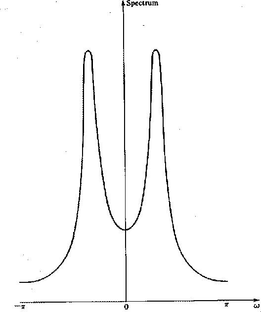
instead of ![]() .Thus, the composite spectrum is the product of
Figure 15 with itself reversed along the
frequency axis. This is shown in Figure 16.
.Thus, the composite spectrum is the product of
Figure 15 with itself reversed along the
frequency axis. This is shown in Figure 16.
|
2-16
Figure 16 Spectrum of a two-pole filter where one pole is like Figure 15 and the other is at the conjugate position. |  |